Tell me something about your amplifier A Wayne
Have you finished....what is the stage your assemble is now a days.
Please, let me know your progress... and tell me if i can help.
I am with a very good mood...nice day outside.... amplifier is sounding great.... huge bass and special treble...clear mids...detailed, focused.... very good... very powerfull.... watch the sunny day in Northeast of Brasil.
regards,
Carlos
Attachments

Last edited:
Nice Cannonica.... very nice.
Thank you.... is good to see your progress...go posting pictures.
regards,
Carlos
Thank you.... is good to see your progress...go posting pictures.
regards,
Carlos
Have you finished....what is the stage your assemble is now a days.
Please, let me know your progress... and tell me if i can help.
I am with a very good mood...nice day outside.... amplifier is sounding great.... huge bass and special treble...clear mids...detailed, focused.... very good... very powerfull.... watch the sunny day in Northeast of Brasil.
regards,
Carlos
Hello Carlos,
I have recieved all my matched output trannies from Evette. Also recieved , PSU caps,transformers and heatsinks. I'm now preparing the chassis for the PSU , before doing any asssembly on the boards.
The transformers and caps are huge, forcing me to do mono bloc's, so more work , 2 chassis instead of 1 .. 🙂
Mucho questions to come ....... 😀
Last edited:
Put in together the other board too slow
I'm sorry guys because I'm going really slow in my project, so far I'm putting together the other board little by little, and the first board is complete I check it a couple of times, and all look alright so far, also another reason I haven't post any results is because I don't have a large heat sink so I really don't want to power up with out heat dissipation that is no go! , but I was thinking to get me a "bench heat sink tester" lol, so I can test the boards dah! , alright my friends have a great day.
regards
vargasmongo3435
Thank you by the report dear A. Wayne and Juan Vargas
I am glad to know your progress.... thank you very much by pictures posted, by the enthusiasm and presence in our thread.
You know guys....i have to say i was wrong related something i have said in some videos and some text posted.
I told that leakage and low capacitance in electrolitic condensers is a rarity..that does not happens everyday and that in 51 years of electronic activity i have never found one with low capacitance or with leakage....and happened...i have found one yesterday.... a low capacitance in a senior, old and tested capacitor
Well....i keep my words about rarity.... at the end... 60 years old and 51 years of audio electronics and this is the first time....but i have to fix...this happens, despite i have not found this kind of evidence before in my life.
I young guy, my daughter's school friend, knows an electronic repair man from a TV repair shop we have nearby our home... he came to my home carrying a big cartoon box, squared, 3 feet size with 3 feet tall, filled with circuit boards all audio circuits... junk parts i love to remove, clean, test, select and use...they are tested parts..special for audio..because used by manufacturers in audio equipment... senior parts... that worked and are something to trust.... and then i found a damaged condenser.... i will make a video showing you the stuff.
Also two Toshiba mini systems (no speakers sadly) and one Aiwa mini system to dismantle.... we sit at my living room ceramic floor,each one of us with our own soldering iron, and we disassemble the boards while chatting..he is one of my audio electronic students....as i am getting old and i am trying to left all i have learn to others.
Juan.... try to switch your amplifier on using 12 plus 12 volts supply..just to check if it is fine.... using low voltage you can power your unit without protective resistors and without heatsink.....this is another way to power an amplifier without the use of heatsink and protective resistors..some amplifier can operate with lower voltage...these modern ones can (from 1992 to our present day... not vintage yet..already modern units).
Evette is a friend....this is his daughter name.... he is Jack.. and his transistors are good..he sent me last year, as gift, more than 30 transistors..all special..all very good.... i am using his transistors in my prototypes, also in my three main amplifiers, a Blame ST and two Supercharged blue boards (made to my sons).
regards,
Carlos
Bad supply condenser and other MKIII Hx red board issues
A video here:
MKIII Hx with a bad condenser...more issues about - YouTube
regards,
Carlos
A video here:
MKIII Hx with a bad condenser...more issues about - YouTube
regards,
Carlos
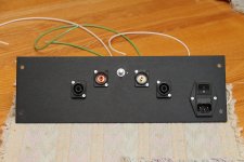
Can I use +24 0 -24 insteed of 12?
Hi mister Carlos!
what about 24V I have one toroidal transformer that supply after rectification and filtering exactly +24 0 -24 volts can I use that?
Hi mister Carlos!
what about 24V I have one toroidal transformer that supply after rectification and filtering exactly +24 0 -24 volts can I use that?
Attachments
Last edited:
Yes you can...but if your transformer is huge, or something
able to supply power... then you should use some protective resistor, values from 10 to 100 ohms...any value is acceptable, in series with positive and negative supply rail.
The idea is to try a low power transformer.... these ones we usually have available from preamplifiers, tape decks and other appliances...small transformers... units that cannot supply too much current under short circuit.
these transformers, for testing purposes, will be good if they have three wires in the secondary, or symetrical voltage.... 9 plus 9 volts, 12 plus 12 volts alternated, 15 plus 15 volts, 18 plus 18 volts and so on...small ones.... when trying big ones..then use resistors in series...because a short in your board will drain all current from the transformer..and a mid size transformer can supply 30 amperes or more under short circuit..and this current may melt tracks from your board.
regards,
Carlos
Last edited:
Transistors strights
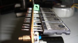
Ok so I got to find a smaller transformer ok I can wait 😛 , well maybe I got to look around to see if I can find one, hey I was thinking how can I install the trannies as straight as possible, so I thought maybe I can use an object under so keep the trannie straight so hell yeah it works good!....lol "muito bom"
regards
vargasmongo3435
Attachments

In the seek for perfection, I've done some adjustments and fine tuning on some components. These are directly or indirectly suggested by Carlos-The-Great
At the bottom is a picture showing 5 mods i've done for it to suit exactly my needs and desire of perfection.
These are:
1st: The 22 ohms CCS resistor have been replaced by a 47 ohms. This has reduced the CCS and VAS heat sink temperatures by about 12 to 15 degres Celcius. Now with boards on the bench, not enclosed, they're stable at exactly at: CCS = 42C, VAS 40,5C. (Ambient temperature is 22C and RH is 40%) I cannot hear ANY difference. I can only recommend this, it's an easy fix for a potentially serious problem. I can't wait to put everything in the chassis to check the temperature rise of these and imagine what it would've been with the initial resistor.
.
Is there anyway to measure these changes, temperature aside what's the down side, more thd for eg ,,,?
Vargas,
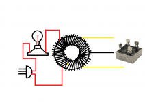
use a light-bulb tester, something like this:

and wire it in serial with the mains.
The light bulb-tester will limit the current flowing into the primaries of the transformator to the value that you chose for the lamp
(for example: 30 Watt). The transformer's output will then be limited to this value as well!
Best regards - Rudi
Last edited:
Yep...the idea is to limit the current.... and the series
light bulb does that too.... it is a very good solution.
regards,
Carlos
light bulb does that too.... it is a very good solution.
regards,
Carlos
There are several possible solutions dear Juan
A variac controling the transformer primary voltage is also a good idea... also people can use two to one transformer...for instance; if you have a 110 primary and a 27.5 plus 27.5 VAC secondary.... so, reduction is 2 to 1... a step down unit....now connect this secondary of 27.5 plus 27.5 volts alternated into your main transformer primary... when this main transformer primary is wired to 110 volts and will receive a half of that...then your output voltage will be reduced to a half.
The idea is to try less power, less voltage, less energy, when testing appliances...sometimes we have shorts in the board...a short circuit may drain a lot of current and this current depends on your supply current...so, if you produce a "sabotage" using a light bulb, or series resistors, or Variac, or step down transformer..then you will supply less energy in order to save your pcboard to be melted.
Sometimes bias trimpot has bad solder..cold joint... cold solder.... or other problem.... maybe a misadjustment in the trimpot...then the current can go to infinite....if you provide infinite current than board will melt...if you provide current your transistors can face..then they will survive...this is the idea..to provide, while testing, small energy in order to save your pcboard or transistors if you have something wrong on there.
I do like portuguese too.... eu gosto de portugues também.
regards,
Carlos
Voltage control
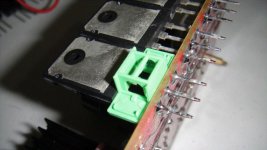
Oh I see, lower current that goes to the PCB track will keep them safe range so they do not act like "fuses", oh by the way my friend, today I finished put in all the trannies, and I have a magnifier and therefore check every single solder pad for shorts I have capture this image with the magnifier,good think you let me know about what would happen if I use to much current, nice man you save my life lol he he he he cool man.
regards
vargasmongo
Attachments

Your picture shows a better condition compared to what i perceived
here... you have cleaned your pcboard, your solder was perfect despite looks that have already some rust on it....the clearance is not that bad.
I have visited the doctor and i have ordered new glasses.
regards,
Carlos
here... you have cleaned your pcboard, your solder was perfect despite looks that have already some rust on it....the clearance is not that bad.
I have visited the doctor and i have ordered new glasses.
regards,
Carlos
- Status
- Not open for further replies.
- Home
- Amplifiers
- Solid State
- Dx Blame MKIII-Hx - Builder's thread