i believe the joints you are talking about are connected by a trace anyway . if that's the case you may break that trace by fixing a problem you really didn't have to begin with 🙂
cheers Woody
cheers Woody
The eyes are not the same...
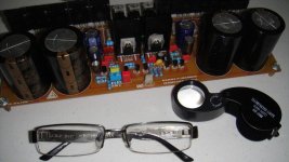
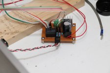
Hi destroyer x you are not the only one, is getting really hard for me to solder, my eyes site get really blurring after 5 minutes looking at the board is really hard to keep steady image of my soldering, by the way how did you know that I wash the board? humm.... interesting.... hey I was looking around at home and I found this transformer with multiple outputs maybe one of them has the voltage a need for testing the board thanks keeping updating me and all the guys from the forum really helpful guys.
regards
vargasmongo
Attachments

Nice pictures dear Juan...thank you
Ahahahaha....you also have a Aiwa micro system power transformer...the same i am using..just remove all shields and you will have the same unit i have.
By the way, my glasses will be substituted, exams already made and lenses already ordered.... i am suffering from aging effects... and this happens with anyone.
I am playing with my test unit.... i have reduced the off set and checking it operating high power to see the thermal control.... the blower is working from time to time.
Here is the last video, this early morning having fun:
MKIII Hx, off set and stand by bias - YouTube
regards,
Carlos
Last edited:
Temporary heat sink
Thank you destroyer, hey I found a piece of aluminum is not big enough but I can use it as a temporary heat sink also some mica insulators but I heard that there are new ones that don't need thermal grease, I guess I got to go "old school" and get my hand dirty lol is ok as longer I don't have a short is all good, about that transformer it has two center tap with different voltages I measure 34V 0 34 on one set and the other 24V 0 24V, maybe I can use it as a "tester power supply", and nice video by the way, take care bro.
regards
vargasmongo
Attachments
Good dear Vargas...soon you will be happy and dancing while
listening this wonderfull amplifier.... sonics are very special and i am sure you will be very happy with it.
I am! ... .and i continue to enjoy and to have fun ... see the video:
Playing the MKIII Hx - YouTube
About your trafo (transformer).... 24 plus 24 will result 34 plus 34 volts after rectification and filtering....and the 34 volts winding will result 48 plus 48 volts dc (after rectification and filtering)... and you can use anyone of these to obtain a 200 to 300 watts RMS power amplifier evaluating your transformer by watching it's size.
Keep volume low...try to keep voltage around 10 volts in your output (10 volts of audio) and install a fan to keep transistors cool down.... important is to keep the stand by current low... if off set is big do not mind..go ahead.
regards,
Carlos
Last edited:
What the hell same trandformer lol wow!
Yes it is the same transformer what an coincidence ! well I have an appointment in veterans today after I got back I will then test it with cautions, later guys
regards
vargasmongo3435
Yes it is the same transformer what an coincidence ! well I have an appointment in veterans today after I got back I will then test it with cautions, later guys
regards
vargasmongo3435
Attachments


Yes Vargas, removing this gray mumetal shield belt
You will have a transformer looking the same as mine..with a copper band around the coil and some nice varnish covering the E/I plates that constitutes.
Mumetal is a magnetic metal...blocks magnetic field i think... a shield..that gray flexible cover... wind it out from the trafo if you want...inside is pretty,.. looks good.
Yep Vargas, you are a veteran from Iraq war.... people should show more respect for a real man you are...good meeting with your buddies.
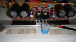
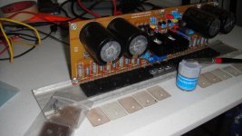
Daughter is here using my PC all time long.... i am waiting her to leave to a party, a cinema or a to go to the beach then i will produce a video about the modifications i have made to use 40 volts supplies.... people may be confused about my small heatsinks and some other details.... i do think this is confusing.
What i did:
I have reduced current to CCS transistor and VAS transistor (these two on board devices that i told you they need bigger heatsinks).... i have increase the 22 ohms resistor to 47 ohms in order to reduce current.... so.... voltage reduce and current reduced results in power reduction..then the small heatsinks will be good.
I have changed the bias resistors a lot.... i am not sure but it seems i have used a 500 ohms trimpot in series with a 600 ohms fixed resistor from base to emitter into the bias controlling transistor..that guy is also the thermal sensor as you know.
I have used low capacitance.... less than 6800uf per rail because to 8 ohms i will not need more than that considering my supply power.... i will not have current demand to ask for more capacitance..it is a single channel only.
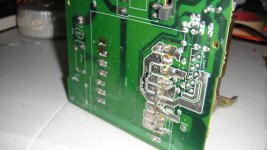
I have used small condenser to the rail... the input condenser, those auxiliary big one where cutted out when i cutted the board extremes out...then i install a small 100n capacitor each rail in place of the auxiliary ones.... after the diodes (now 1N4007 x2 installed in the copper side) i am using 470uf/35V to each rail.
Gain resistor is 350 ohms instead of 390 ohms and i do think i should replace by a 220 ohms because i am using MP4 player to test the unit there in the junk room.
I am using only a single pair because i do not need more than that to my supply voltage and my speaker impedance.
My main target was to check the main circuit.... bass is lovely... i do think this one beated the Dx Blame ST in the bass area..... now it is the best audio amplifier i have ever listened too.... the treble is wonderful and can be better.... i am using 220pf as miller capacitor (compensation) and i do think i can reduce to 82pf......but i am afraid to do these modifications because my scope is damaged and i cannot inspect the waveform to know if everything is fine.... reducing the capacitor we gonna have much more treble transparence, presence, power in the treble, detail and some harmonic reduction that may turn the sound of a bell much better...also hit hat, breath and voices breath.
regards,
Carlos
You will have a transformer looking the same as mine..with a copper band around the coil and some nice varnish covering the E/I plates that constitutes.
Mumetal is a magnetic metal...blocks magnetic field i think... a shield..that gray flexible cover... wind it out from the trafo if you want...inside is pretty,.. looks good.
Yep Vargas, you are a veteran from Iraq war.... people should show more respect for a real man you are...good meeting with your buddies.
Daughter is here using my PC all time long.... i am waiting her to leave to a party, a cinema or a to go to the beach then i will produce a video about the modifications i have made to use 40 volts supplies.... people may be confused about my small heatsinks and some other details.... i do think this is confusing.
What i did:
I have reduced current to CCS transistor and VAS transistor (these two on board devices that i told you they need bigger heatsinks).... i have increase the 22 ohms resistor to 47 ohms in order to reduce current.... so.... voltage reduce and current reduced results in power reduction..then the small heatsinks will be good.
I have changed the bias resistors a lot.... i am not sure but it seems i have used a 500 ohms trimpot in series with a 600 ohms fixed resistor from base to emitter into the bias controlling transistor..that guy is also the thermal sensor as you know.
I have used low capacitance.... less than 6800uf per rail because to 8 ohms i will not need more than that considering my supply power.... i will not have current demand to ask for more capacitance..it is a single channel only.
I have used small condenser to the rail... the input condenser, those auxiliary big one where cutted out when i cutted the board extremes out...then i install a small 100n capacitor each rail in place of the auxiliary ones.... after the diodes (now 1N4007 x2 installed in the copper side) i am using 470uf/35V to each rail.
Gain resistor is 350 ohms instead of 390 ohms and i do think i should replace by a 220 ohms because i am using MP4 player to test the unit there in the junk room.
I am using only a single pair because i do not need more than that to my supply voltage and my speaker impedance.
My main target was to check the main circuit.... bass is lovely... i do think this one beated the Dx Blame ST in the bass area..... now it is the best audio amplifier i have ever listened too.... the treble is wonderful and can be better.... i am using 220pf as miller capacitor (compensation) and i do think i can reduce to 82pf......but i am afraid to do these modifications because my scope is damaged and i cannot inspect the waveform to know if everything is fine.... reducing the capacitor we gonna have much more treble transparence, presence, power in the treble, detail and some harmonic reduction that may turn the sound of a bell much better...also hit hat, breath and voices breath.
regards,
Carlos
Last edited:
Guys,
May i suggest when discussing changes to reference part number along with resistor/capacitor value..
Makes for less mistakes .....😕
Also which are the correct values , the part's list or what's listed on the board ..?
May i suggest when discussing changes to reference part number along with resistor/capacitor value..
Makes for less mistakes .....😕
Also which are the correct values , the part's list or what's listed on the board ..?
A. Wayne...if this is to me, please, explain in more details what you mean
and what you want.
Do you want reference numbers?.... the values printed into the board?.... pictures showing.... video detailing.... schematic on screen?
What is the correct values?.... the ones printed into the board are fine...they where the reference to Byron to produce the part's list or bill of material.... also no one is the correct value when i have made a special low powered version to allow me to test the circuit..the main circuit..the heart of the circuit, the most important part.... board sides, if you watch my videos, are there to install more power transistors in order to allow us to use higher voltage from the supply, to allow us to use lower impedance than 8 ohms..to use the amplifier full power as a heavy duty unit.
I do not appreciate bureaucracy, reason why i use to say the schematic is the reference...my circuit is my circuit, to avoid confusions i told the changes i made to MY CIRCUIT, my personal, exclusive, home unit, made for testing purposes..to test the main circuit, the core, the heart of the circuit.... this is not for others to make...it is just explaining that changing supply voltage we have to change a lot of things altogether.
I am not releasing a new diagram of a low power version...so... no schematic, no part lists nor bill of material..... in the reality i have never made bill of material...others asked and the ones where interested have prepared part's list or bill of material...i do not do that because i do think the schematic is more than enough to inform the capacitance, and the voltages are the rail voltages or supply voltages (insulating voltages for condensers) and when there are different demand of voltage i use to explain...usually the bootstrap condenser and the NFB condenser are rated to rail to rail voltage...others are for rail voltage.... resistors are all 1/4 watt unless other remarks made at the component and printed in the schematic.
The preparation of part list does not make sense (to me) when we have the schematic.... people have just to watch and write in a sheet of paper the component value, and insulating voltage...so...the tool is offered..the guy should just move and work a little.
regards,
Carlos
Last edited:
Hello Carlos,
Not directed at anyone person, more for public discourse, when referencing parts. IMO , if we say C15 or R22 for eg. and then the value for the changes. This would facilitate changes/updates to our BOM or schematics, for accuracy..
Question on C15 (470UF) would we have an ripple issue if this value was increased or decreased. I had intended to raise mine to 680uf ..
Regards,
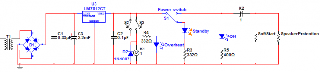
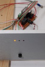
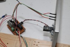
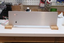
Worked few hours on the front plate. I wanted to keep it simple...
Three LEDs and one small-current 12V pushbutton for power on/off.
Left LED is AMBER and is for standby.
Middle LED is BLUE and is for power-on.
Right LED is RED and is for overheat.
I've made a small logical circuit that will manage the LEDs, the overheating situation and the power on/off. This circuit will feed the softstart and the loudspeaker protection circuit. This circuit will always be powered; it's powered by its own small 15VAC/20VA trafo (I have a master switch at the power-entry module that will remain to the ON position to feed it). You can see in the schematics that whatever the position of the on/off switch is, the power is interrupted on overheating condition and the standby/power-on LEDs are still showing the actual status of power-switch.
Some pics below...
Attachments
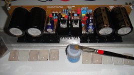
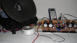
Dear friends I'm happy with my first Dx Blame experience!
Dear people,
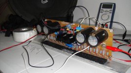
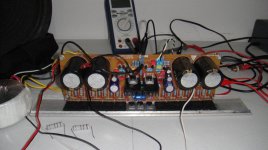
Finally I tested the first board last night and I was amazing that works the first try, only using +24 0 -24V, the woofer you see is 8 ohms, and about describing the sound it was really nice and amazing so clear voices, drum bass, at the biggining I was to be honest afraid that something might go wrong but I remember the resistor on the fuses area so I solder them, and no matter what, music came out nice and clear!.... but the must amazing thing is that there is no homing sound coming out from the woofer completely silence, I was playing some different types of music and I do notice the difference this baby reproduce any type of sound notes!
really precise, the woofer is 15 inches and it was moving hard for the first time in many years wow!, also I check for CCS heat sink temperature and it didn't get even warm at all probably because I'm not using the correct supply but yes my friends and happy that it went well, another thing tomorrow I will try using the other toroidal that supplies +54 0 54V after rectification and filtering to see how it reacts of course I have to check the heat sink again to make sure the thermal paste is in contact with the main transistors, and I got to check the emmiter voltages this time lol
 wooohoooooooooo!
Ok my friends have a good one thanks for all the tips and advices specially
mister destroyer x!, alright have a good one guys.
Regards
vargasmongo3435
Dear people,
Finally I tested the first board last night and I was amazing that works the first try, only using +24 0 -24V, the woofer you see is 8 ohms, and about describing the sound it was really nice and amazing so clear voices, drum bass, at the biggining I was to be honest afraid that something might go wrong but I remember the resistor on the fuses area so I solder them, and no matter what, music came out nice and clear!.... but the must amazing thing is that there is no homing sound coming out from the woofer completely silence, I was playing some different types of music and I do notice the difference this baby reproduce any type of sound notes!
really precise, the woofer is 15 inches and it was moving hard for the first time in many years wow!, also I check for CCS heat sink temperature and it didn't get even warm at all probably because I'm not using the correct supply but yes my friends and happy that it went well, another thing tomorrow I will try using the other toroidal that supplies +54 0 54V after rectification and filtering to see how it reacts of course I have to check the heat sink again to make sure the thermal paste is in contact with the main transistors, and I got to check the emmiter voltages this time lol
wooohoooooooooo!Ok my friends have a good one thanks for all the tips and advices specially
mister destroyer x!, alright have a good one guys.
Regards
vargasmongo3435
Attachments
Last edited:
Great news from Cannonica and Vargas
Thank you guys as you are sharing pictures and reviews about the unit.
Good this circuit you made Cannonica...congratulations.
It is awesome when we put parts together and we make them work.... this is creation...we feel alike God creating things...nice feelings.... enjoyment, pride, satisfation, happyness...the success!
regards,
Carlos
First Video testing sound
Hi guys here is a link of the first test with MKIII Hx is so amazing first go on my first attend lol my camera is not able to capture all the sounds but in real life oh my God out of this world!!!
here is the link: http://www.youtube.com/watch?v=s5pt0_9bCMk
regards
vargasmongo
Hi guys here is a link of the first test with MKIII Hx is so amazing first go on my first attend lol my camera is not able to capture all the sounds but in real life oh my God out of this world!!!
here is the link: http://www.youtube.com/watch?v=s5pt0_9bCMk
regards
vargasmongo
hahaha!! damn, put that speaker in a box so we can hear the true music 😀
Anyways, congrats on your build.
Anyways, congrats on your build.
I wish a have one bro
I have another speaker with the box I'm making another video
hahaha!! damn, put that speaker in a box so we can hear the true music 😀
Anyways, congrats on your build.
I have another speaker with the box I'm making another video
Great....more videos..... more!
Yessssss!
Use a coil in series with your woofer dear Juan.... 250 turns of 1 mm wire inside air core, can be air core from medicine adhesive, some band aid reel or similar.... this will cut mids and treble to the woofer, you also can install two 220uf in series (but back to back in polarity, plus connected to plus) and them solder this guy into your woofer terminals.... use 22uf (bipolar) or two 47uf back to back in series with the red wire (live wire of audio) and them you gonna block bass and midranges and then send mids and treble to this tiny monitor speaker you used in your recording...it seems it is able to reproduces nice treble and maybe a good midrange too...install the woofer in an enclosure because it is having front to back phase cancellation.... this kills bass.
220uf condensers in series, even back to back, will result in 110uf...this will "eat" some remaining treble and upper midrange frequencies the coil could not block (filter).
22uf will let mids and treble to cross..the tweeter, inside your speaker enclosure, already have it's 2.2uf or 4.7uf capacitor...so, you need only to install the 22uf...if you feel needed, then use 8 ohms (or something alike) in series with your mid/high drivers...to make the bass comes true.
This is the way i use at my home and works fine.... this is standard, traditional, and this way is used for more than 80 years..since the radio age.
thank you very much...make more.... much more...yesssssss!
regards,
Carlos
Last edited:
muito obrigado destroyer x!
Of course my friend! I made a video with low frequencies test and but before that I was playing music for about 3 hours! many types of music, rap classic, electronic music, bass , rock etc... seems to me that this baby can handle anything you put on, and the woofer you see in the video I bought it like 8 years ago and is the first time that the voice coil warm up! no bulsh#$%t the woofer is rated 1.5KW 8ohms! the supply voltage when up and it helps a lot more bass output than yesterday and that coil is 4" in diameter so I imaging this with the right set the filters that you mention well set up, oh my lord!!! to much emotions my brother!!! ok I got to find some caps and 1mm wire to do that is just awesome man thanks for the tip.... hell yeah! muito obrigado....
regards
vargasmongo3435
- Status
- Not open for further replies.
- Home
- Amplifiers
- Solid State
- Dx Blame MKIII-Hx - Builder's thread