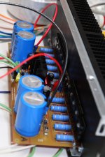
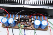
Today a did some changes on my layout, I change the heat sink for a taller ones and the silk screen too, of course this is Alex MM layout don't get me wrong that is the man! well I got to keep looking analising and all that, I hope you guys like my ideas, "I hope so" lol , alright guys have a good one. 😛
Vargas,you gave me an idea thanks🙂
Today a did some changes on my layout, I change the heat sink for a taller ones and the silk screen too, of course this is Alex MM layout don't get me wrong that is the man! well I got to keep looking analising and all that, I hope you guys like my ideas, "I hope so" lol , alright guys have a good one. 😛
what are the changes , support pads for the heat sinks ..?
I just got the heat sink today, it take forever to get parts here in Puerto Rico ! well I got to have patience.
What brand resistors are you using ..... 🙂
taller heat sinks
taller heat sinkswhat are the changes , support pads for the heat sinks ..?
those are from eBay must of them but I use the wrong wattage they are 1/2W instead of 1/4W is ok for me. the brand 1 2w Watt 3.6k ohm 3k6 Metal Film Resistor 0.5 W 200 items in abillionstore store on eBay! no promotion, to them just information.
There is not much I can do on Alex MM layout is already good, I can not change numbers or position of components I move some stuff a bit not much for my personal layout, "heat sink taller" that is all I got in my mind guys lol have a good day guys.
Regards
vargasmongo
Regards
vargasmongo
Last edited:
My dear friend Juan Vargas is helping a lot.
He use to make his layouts based in Alex mm and other layout designers.
He does that because he loves to learn the stuff, and his progress in this kind of stuff is awesome.
He is a humble man that does not want to bother Alex mm or other designers, he just want to learn and he start from something already made.
He is the one bought boards from group buy and loves audio and to build things.... he does not think his layouts are better, reason why he use to buy board from more skilled layout designers.
He does not point errors..he just suggest things to make the layout better..without criticisms... clearly trying to help.
I have to thank dear Juan by his help, as i am really needing someone to fix that stuff connected to the clearance to install bigger heatsinks.
I need to cool down these transistors that are on board, the CCS to VAS and the VAS transistor itself...or increasing heatsink size (larger and taller having more are exposed to the air, with more fins), or someone to suggest modifications to install these transistor below the board (Cannonica did that...thank you Cannonica), or other clever solution.
I have to thank all of you by the confidence, support and help...you know.... we have a problem.... these heatsinks (clearance, room for them, free space to install heatsink on board) are not good enough.
regards,
Carlos
Attachments

Last edited:
CCS/VAS heatsink options
Did some searching on the Fisher-website and found some
heatsinks that could be usable for CCS/Vas cooling..
From left to right:
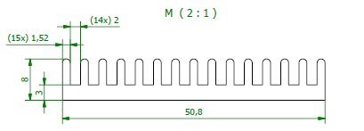
SK427 - available in 50 and 75 mm height, would fit the pcb without modifications.
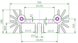
SK459 - 50 mm height, would require some modification of pcb or maybe use short wires.
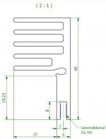
SK576 - 25 mm wide so you would need two, and would cover some components.
Link to the Fisher website:
Fisher Website
Regards,
Klaas
Did some searching on the Fisher-website and found some
heatsinks that could be usable for CCS/Vas cooling..
From left to right:
SK427 - available in 50 and 75 mm height, would fit the pcb without modifications.
SK459 - 50 mm height, would require some modification of pcb or maybe use short wires.
SK576 - 25 mm wide so you would need two, and would cover some components.
Link to the Fisher website:
Fisher Website
Regards,
Klaas
Attachments
Thank you Klaas
This helps .... Juan have also published things about the same subject.
Very good
regards,
Carlos
This helps .... Juan have also published things about the same subject.
Very good
regards,
Carlos
Hey guys I made this small video dedicated to my friends who were working hard to make this MKIII latest creation possible, if they were more people involve to it thanks to all of them, I hope you like it guys my proyect is not complete but at least I'm part of it, thank you guys. here is the link video:
Dx Blame MKIII Hx Carlos Mergulhão circuit designer - YouTube
regards
vargasmongo
Dx Blame MKIII Hx Carlos Mergulhão circuit designer - YouTube
regards
vargasmongo
Hi vargasmongo,
I have seen this morning via your video that you use Elna For Audio 10000uF/80volt.
If you have a datasheet of that, you can post it here so that other people also may watch that these caps are not fake.
If there is a datasheet I order also those Elna for audio.
When I finished the amplifier I swap NICHICON for the Elna for audio and listen which one is the best.
I received no response from Elna America.
Regards,
Rudy
Actually those are eBay capacitors so I took a risk to buy those on my own risk, but after I got them they were really heavy so I don't think they are fake, I will check to make sure jsut in case.
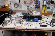
Things are coming together!
Carlos' U-tube video made me laugh when it started "Uncle Charlie, my amplifier does not work". Like the video told me to, I just went through it piece-by-piece, checking everything with multimeter or capacitor tester. I eventually replaced several parts. I exchanged the small ceramic disk caps for 100V caps that look like plastic blocks, and replaced some transistors, and cleaned up some questionable soldering.
I'll never know just what the problem was, but when I fired it up, I was able to adjust the voltage drop across the 100R resistors to 4.1V. When I hooked a speaker and some music up . . . viola!
The chassis finally arrived Thursday, so now I have two working boards, a chassis, and a weekend ahead of me!
oh yeahhhh
It may not look like, but this one is playing Sultans of Swing
I'm really happy, it's a one on one, everything went smooth and worked the first time (I cross my fingers for the second channel).
The only thing is that my Fluke 73 multimeter cannot measure the bias voltage at the output resistors. It seems its sensitivity doesn't permit that.
After measuring 3.1V at the startup 100R resistors and a few millivolts of offset, I decided to put the fuses into place and connect my iPod to the input. First sending a sinusiodal signal (using a signal generator) of 60Hz to measure "alternative" voltage at the speaker out. Just to check that it was amplifying and that my input pot wasn't upside down. I then switched to a musical program and plugged my speakers.
Seems to sound very good even without adjusting the bias. I didn't cranked it yet, everyone is sleeping in the house actually 😛
As expected my CCS and VAS heatsinks are between warm and hot, but I can leave my fingers and it doesn't hurt. It's definitively hotter than "human fever". I'll see what I'll do... but I guess I will leave them like that and see once the amps are in their cabinets how they go.
Now gotta put the second channel onto the main heatsink and expect it to work like the first one...
Some pics below.
- A happy Canonnica. Martin.
Attachments


People is having progress..... this is wonderful
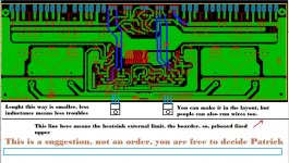
The track length may be a problem dear Patrick....if possible, change the position to nearby the input, this way the board can go upper, more atop of the main heatsink in order to produce clearance to these two transistors.... well...if less than 6 centimeters...then no problems....but your solution was fine... double face board?... copper track both faces? .... very good, but this may be expensive ... well ..... if needed this way, then go ahead and thanks.
I am happy reading your message dear Byron .... i was sad you had troubles ... now i am fine ... enjoy.
Cannonica - MP3/4 players, Ipods and so on, use to have lower audio output level, exception is if you use the line out output jack ... having low level in the input you will not reach full power, then you should reduce the gain resistor connected to the second differential transistor base .... the feedback one ... the one you have connected to the output line through a 47K resistor.... Sultans of Swing is also one of my main test songs.... thank you very much by your support, confidence in Dx amplifiers and also your enthusiasm.... pictures are nice..thank you, go ahead posting...more!
Very appreciated your activity Juan ... continue posting things and pictures.
regards,
Carlos
Attachments
Last edited:
If your Blame is not working... do not fear ... uncle charlie is here!
Here is the video about:
My Blame amplifier is not working uncle charlie! - YouTube
regards,
Carlos
Here is the video about:
My Blame amplifier is not working uncle charlie! - YouTube
regards,
Carlos
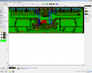
These are just some try outs to learn the software.About 2 layer boards isn't that much differents in costs not a reason for not using it.I've one more idea but I've to ask Alex how to do it in SprintLayout.Will keep on trying.
- Status
- Not open for further replies.
- Home
- Amplifiers
- Solid State
- Dx Blame MKIII-Hx - Builder's thread