
not yet
My soldering station is broken. and I'm too cheap to pay retail for a new one. So I'm waiting on an e-bay auction.
My soldering station is broken.
and I'm too cheap to pay retail for a new one. So I'm waiting on an e-bay auction.My soldering station is broken.
hey byron , i keep meaning to but a new haako but because this Stahl Tools SSVT Variable Temperature Soldering Station 374-100 just keeps working great . the cord could be a lil more flexible but otherwise . they also sell a cheap set of tips . i like the small chisel one .
cheers Woody
It's funny you should say that, because this Stahl Tools soldering station
Stahl Tools TCSS Temp Controlled Soldering Station ESD Safe 374-200
is the one that just broke!
I'm bidding on a Weller which retails for $125 right now.
Stahl Tools TCSS Temp Controlled Soldering Station ESD Safe 374-200
is the one that just broke!
I'm bidding on a Weller which retails for $125 right now.
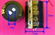
Elna 10000uF 80V For Audio Capacitor
I wish to order 8 of these, Elna 10000uF 80V For Audio Capacitor on the Dx Blame MKIII-Hx board but are these good caps or can I order better other brand caps, I need the 80 volt?
I can order these for a good price $10 each but the country is china, I hope these caps are not fake.
Is there a list for fake components from china?
Regards,
Rudy
Attachments
If you are on UK 240Vac supply and use a 230:40Vac 5% regulation transformer then you find that the maximum DC across the smoothing caps can rise to ~62Vdc. This just allows a 63Vdc cap to be used.
Any higher than 40Vac and you should use the next higher cap rating.
35diam * 50 tall, seems small for an audio cap of 10mF & 80V.
Have you checked ELNA data to see what the size is?
Any higher than 40Vac and you should use the next higher cap rating.
35diam * 50 tall, seems small for an audio cap of 10mF & 80V.
Have you checked ELNA data to see what the size is?
Hi Andrew,
Thanks for your answer, my Transformer is 42Vac 2000Va and I have 2 of them.
Is there a good alternative for these 10000uF 80 volt caps on the Dx Blame MKIII-Hx board.
Have somebody experience with good quality caps on this place of the board?
Regards,
Rudy
Thanks for your answer, my Transformer is 42Vac 2000Va and I have 2 of them.
Is there a good alternative for these 10000uF 80 volt caps on the Dx Blame MKIII-Hx board.
Have somebody experience with good quality caps on this place of the board?
Regards,
Rudy
42Vac, 3to 4% regulation, on a 220/230Vac mains system must operate very close to 63V. I would not run 63Vcaps.
I think you have made the correct choice going for 80Vdc rating.
Have you checked Elna's datasheet?
I think you have made the correct choice going for 80Vdc rating.
Have you checked Elna's datasheet?
Still no joy
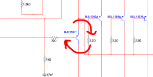
I removed the suspect filter caps, and replaced all the transistors. I carefully checked everything. I measure ~0.6VDC across the 100R test resistors. The trimmer resistor has no effect. I'm out of ideas. The voltage across all of the output resistors is 0. I checked my power supply again, and it's good.
The plan now is to start building the second board, checking every component with multimeter or capacitance tester before and after inserting it.
One curious finding: that jumper/optional 10ohm resistor connecting signal ground to high-power ground: I measured ~35VDC across those holes when it was open. That seemed a bit high. Is that voltage in the right ballpark?
-Byron
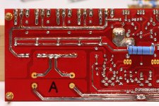
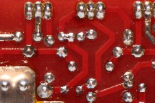
If it can be of any help, try photographing the solder side of the board. It's easier to find something wrong this way instead of looking with naked eye.
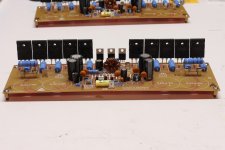
See the attached pictures, one is a the original framing at reduced resolution, the other is a crop at full resolution.... And one more to show my advancement. Still missing the small heatsinks. And I'll wail until the output transistors are screwed to the main heat sink before soldering the filter caps, for easier access.
Martin.
Attachments
Last edited:
Hey canonnica where did you get those beautiful blue resistors and also the PCB stand up? , by the way gorgeous board really nice presentation.
regards
vargasmongo
regards
vargasmongo
Thanks for the suggestion Canonnica. I tried that, but my digital camera just isn't good enough to see anything I can't see with my eyeball. I'm focusing on that crackling sound I heard when I first powered up the board. I'm sure something is fried. I just have to find it . . .
-Byron
-Byron
Hey canonnica where did you get those beautiful blue resistors and also the PCB stand up? , by the way gorgeous board really nice presentation.
regards
vargasmongo
The 5W resistors are Xicon 286-0.47-RC, 286-10-RC and 286-100-RC ordered from a well-know US distributor 😉 . I didn't want wirewound resistors. The PCB standoffs are only there for board assembly as they won't permit clearance of under-board resistor once screwed to the chassis.
It's my very first built 🙂 ... and as Mr. Carlos says in one of his video, because I'm new to amp building, I have a lot of respect to all the steps, components, design, etc... I take all the time that's required, I'm not in a hurry, it's a pastime.
I'm spending a lot of money and time into this project, I want it to succeed.
Martin.
Last edited:
The 5W resistors are Xicon 286-0.47-RC, 286-10-RC and 286-100-RC ordered from a well-know US distributor 😉 . I didn't want wirewound resistors. The PCB standoffs are only there for board assembly as they won't permit clearance of under-board resistor once screwed to the chassis.
It's my very first built 🙂 ... and as Mr. Carlos says in one of his video, because I'm new to amp building, I have a lot of respect to all the steps, components, design, etc... I take all the time that's required, I'm not in a hurry, it's a pastime.
I'm spending a lot of money and time into this project, I want it to succeed.
Martin.
You did a very nice job so far🙂
Dear Byron, i understand that your science is complicated and you search for clues
and tracks to understand what is going on.
Try not to apply your Biological methods into audio electronics because audio is much simpler than that.
The analisis about the presence of 35 volts there can be a result of thousands of mistakes, or circuit errors, or missing parts or mistaken parts, or wrong polarity.... do not try to discover starting from 35 volts there...you will become crazy ... this is alike to count starts in the sky without a map to register the ones where already counted.
Solder your circuit once again (crack sound)
Check your parts, if PNP is in place and NPN is in place if they are not wrong.
Check values, check transistor labels, check if they are inserted in the correct place, follow tracks and check if base is in the correct place, connected to base components, check colector too..and them emitter will be automatically checked.
Check diode polarity
Check if you have missed jumpers
Check your supply polarity....be sure positive is going positive and so on.
Check if your transistors colectors are INSULATED from the heatsink...use continuity buzzer for that purpose.
Watch your board against strong light, can be sunlight or a lamp... observe if you have shorts, could not see, then clean your board with Kerosene (aviation fuel or other petrol solvent) and check carefully.
Check solders, they must be shining, nice shinny surface, the opposite you have in the moon.
Check audio amplifier is simple is you do not engage your brain....this is not something to think about clues....waste of time...takes too much time...this is simple, mechanic work, automated check work, does not need intelligence, better to be stupid doing that because will save a lot of time..it is a matter of find parts in wrong position, missed, bad joined to the other parts...reduce your brain activity, use eyes, board layout to watch, schematic to obtain more details and to check values printed into the component coloured strips.
Hard work, simple work alike to wipe a floor and check if in the dust you have some parts that should not go to the trash box ....just to watch and check.
If you try to study scientifically...they you will become crazy, as all voltages will become crazy if something is wrong.... alike human body.... cannot know the cause when the body is going to die....blood pressure goes crazy, heart rithm goes mad, temperature changes, liver stops, stomach produces strange fluids, intestines starts to move, flesh shakes, eyes starts to roll... general breakdown..... the moment is not to think about causes.... it is waste of time...have to force heart to operate.... inject oxigen, force circulation...keep the man alive..... and after stabilization to think about causes.
I have worked in repair for Motorolla radios (12 years long)..... we concluded that check parts and subcircuits without think about could reduce 90 percent the time to repair....so...why 35 volts is there will confuse and spend time...check parts.
regards,
Carlos
Hi Byron
Those two holes must be connected with an jumper , it's quite unusual to make mesurement in such manner....😕 I think my PCB it's ok , some guy have started this amplifier and everything it's correct from my point of view .
Good luck with your work....🙂
Regards Alex.
Those two holes must be connected with an jumper , it's quite unusual to make mesurement in such manner....😕 I think my PCB it's ok , some guy have started this amplifier and everything it's correct from my point of view .
Good luck with your work....🙂
Regards Alex.
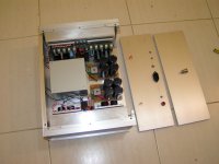
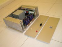
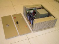
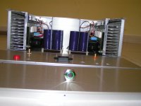
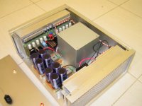
My progress
Sluggish progress due to office work but i did something last weekend. Not wired yet maybe again in the next few days I will do it. and Byron the Amp is workign really fine and sound fantastic you can find the culprit by checking what carlos mentioned.
Sluggish progress due to office work but i did something last weekend. Not wired yet maybe again in the next few days I will do it. and Byron the Amp is workign really fine and sound fantastic you can find the culprit by checking what carlos mentioned.
Attachments
Last edited:
- Status
- Not open for further replies.
- Home
- Amplifiers
- Solid State
- Dx Blame MKIII-Hx - Builder's thread