Very unkind comment BV, your should try to be more educated
We are putting the wheel to run.... others, maybe you, will prefere to sit over the wheel.... i hope with some pleasant moments with the wheel, you may turn more kind.
Not having anything clever, or kind to say, it is better not to say things.
Carlos
We are putting the wheel to run.... others, maybe you, will prefere to sit over the wheel.... i hope with some pleasant moments with the wheel, you may turn more kind.
Not having anything clever, or kind to say, it is better not to say things.
Carlos
Last edited:
Reinventing wheel, gentlemen?😛
http://www.diyaudio.com/forums/solid-state/160061-slones-11-4-blameless-7.html#post2072563
It is very old idea, in many books and schematics. And capacitive loading VAS with 470pF to GND is very suboptimal way to stabilize amplifier- loading means increased distortion at higher frequencies.
Hi, bv..
The idea is way older than slone or doug selfs designs..
as far as i remember, it was vastly used in japanese
amps by the 70s, so the reference you mention also
reinvented this wheel...
Anyway, what was discussed was not the enhancement
of the Vas, but the current limitings around this stage..
About this, i will add that a resistor in serial with the bc546
protect only this one from excessive currents, while using
a zener allow current limiting of both bc546 and bd139 vas.
Hi Carlos
Perhaps you could put a resistor at the collector of Q6, to drop some voltage and share the power?
Regards - Godfrey
q6 is effectively a constant current fed emitter follower.This idea work, godfrey, but then, this transistor s collector will see a signal appearing due to the transistor functionning in a common emitter mode.
So a capacitor should be added in paralel with this resistor to keep
the collector in ground in AC mode...
A resistance in the collector to ground lead will see a nearly constant voltage drop even when the VAS and it's EF are passing audio signals.
Add in this extra resistor to limit the dissipation in the To92 device. I think this was suggested about 5months ago.
BV is right, capacitive loading of VAS to GND is probably the worst possible compensation method.
BV is right, capacitive loading of VAS to GND is probably the worst possible compensation method.
Agree, pavel , but only in the case of a single differential amp.
With a symetrical differential, Vas collector to ground compensation
can work quite well.
Hi, wahab
It was no reference, only example how can it (current limiting in VAS) be done other way, avoiding also VAS saturation and rail" sticking"..
It was no reference, only example how can it (current limiting in VAS) be done other way, avoiding also VAS saturation and rail" sticking"..
Anyway, loading VAS iwith capacitor is worsening its linearity and SR, excessive current is needed.Vas collector to ground compensation
can work quite well.
Last edited:
BV is right, capacitive loading of VAS to GND is probably the worst possible compensation method.
Pavel (and BV, and Eva too for that matter),
I thought it was obvious given how many years Carlos has been here talking about this, but apparently not, so listen up: Carlos has priorities with his projects:
1) great sounding amplifier
2) stable within reason
3) easy and cheap to build for anyone
You will notice there is no mention of distortion in that list. There are other threads for that. Eva, I refer you to item #3.
..Todd
Last edited:
Hi, wahab
Anyway, loading VAS iwith capacitor is worsening its linearity and SR, excessive current is needed.
Well, i m somewhat off topic, but just want to mention that
i used to think so as well till i did some tries and had some
good results with this much decried way of compensation scheme.
As i mention it, it didn t work with simple differential topology
but with a symetrical differential ,it yielded some fairly good
specs when the amp wa loaded with a complex load...
Last edited:
Carlos has priorities with his projects:
1) great sounding amplifier
2) stable within reason
3) easy and cheap to build for anyone
He is not the only one, so please refrain from empty words. We are trying to point at obvious mistakes, I have not said a simple word about THD.

Hi Carlos
Perhaps you could put a resistor at the collector of Q6, to drop some voltage and share the power?
Regards - Godfrey
Yes, during the development of the SiliconChip ULD Mk 2 (a blameless amp), they found Q6 would blow if the amp was overdriven. In their case they found a tight fitting RCA connector on the input disconnected the earth before the positive was causing the problem.
They fixed it by adding a 22K resistor in the position you suggested.
regards
Removed, after strong pression people did, the capacitor that loads VAS
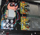
The amplifier passed all torture tests....the room is a mess, wires all around, solder spots, parts replaced...dirty place.
I am here to inform you the Toroidal transformer could not resist the test..also it was presenting noises, maybe some internal bad solder, not a good contact, it was putting dirty in my scope and was driving me mad!.....now everything is fine.
Wave shape good.... sinus becoming triangle only above 150 kilohertz.... low frequency response fine...but really i have lost something i cannot define yet..quality losses when i reduced current to first VAS and the emitter resistor at second stage VAS....well.... at least was not destroyed.
I really think i have to offer something safe...and this is what i am doing...but really, to my own use, my home use...my sound amplifier, then i will remove the modifications and will go back to the Dx Blame ST...the stable one, without the capacitor (10pf) loading second VAS.
Sound is clearly superior to average amplifiers...but this way it is now... the last VAS modified, ..... seems something gone.... there's no more that feeling of transparency i felt before....maybe i am just deliration....not uncommon to do that...we are humans....a lot of modifications...so, i am expecting changes..maybe nothing has changed...i will try to check this doing comparison and calling friends to help me to judge.
The problem i am facing is...the most stable, the most safe one..seem not to be the best sounding one.
Dx Blame ES was unstable to high levels of high frequencies..but sounded better than this Dx Blame ST and better than Dx Blame ST with these VAS modifications.
Leds have introduced too much noisy (audible) and where not needed...thank you by the suggestion.
regards,
Carlos
Attachments
When we follow standard practices of design/creation of amplifiers
we have, as a result, a standard amplifier in sonics..this is what i am realising these last monthes.
The crazy Dx Blame ES..... that could not face high levels of high frequency in the input..sounded much better than this last one......i have to check this comparing next days.
If confirmed, then i will go back to the first one..and will take the risks to have it burned because strange sources of audio with high levels or treble.
I will go inside my own home..my own risks, but i do not suggest you to do the same....i accept to go fixing from time to time to listen that lovely sound.
But for forum folks, builders and friends, my obligation is to offer the most reliable one, the most simple one, with a good sound reproduction.
regards,
Carlos
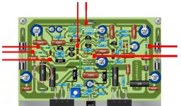
Modifications..... the 15 ohms second VAS emitter resistance
depends to cut the trace to solder the new resistance...this is not a pretty thing to be done...as i could not have it burned during my tests with 44 volts.... i think it is safe the way it is (BD139, second VAS transistor)...so.... not needed to include the 15 ohms resistance, to avoid to cut the board trace.
I am feeling the bass stronger..the treble has lost some level, it is there, but a little bit shy compared to the previous amplifier...the Dx Blame ES.... this is not final conclusion.... friends will help me...i have my own prejudices, so, i need people more able to judge this..so, i will keep one channel without modifications and will switch from one and other to the people will evaluate....maybe next week.
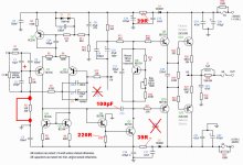
Yellow marks shows parts modified...no copper track to be cutted..parts are just removed or substituted by others..so..board is keep the way it is.
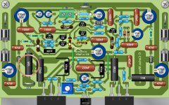
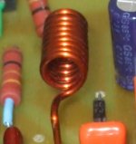
The coil removal is effective to reduce a small noise.... alike overshot.....do not influence sonics...so...not really needed to move coil.... some shield may be a nice idea... the coil shown in the Todd Johnson's artistic view is better than my own.... i am showing mine....better to build alike Todd have painted in the beautifull image he made.
regards,
Carlos
depends to cut the trace to solder the new resistance...this is not a pretty thing to be done...as i could not have it burned during my tests with 44 volts.... i think it is safe the way it is (BD139, second VAS transistor)...so.... not needed to include the 15 ohms resistance, to avoid to cut the board trace.
I am feeling the bass stronger..the treble has lost some level, it is there, but a little bit shy compared to the previous amplifier...the Dx Blame ES.... this is not final conclusion.... friends will help me...i have my own prejudices, so, i need people more able to judge this..so, i will keep one channel without modifications and will switch from one and other to the people will evaluate....maybe next week.
Yellow marks shows parts modified...no copper track to be cutted..parts are just removed or substituted by others..so..board is keep the way it is.
The coil removal is effective to reduce a small noise.... alike overshot.....do not influence sonics...so...not really needed to move coil.... some shield may be a nice idea... the coil shown in the Todd Johnson's artistic view is better than my own.... i am showing mine....better to build alike Todd have painted in the beautifull image he made.
regards,
Carlos
Attachments
Last edited:
No more modifications will be made..final schematic.
further modifications only if i found errors in the schematic..but update and upgrade are closed.
Now people can build and have a very safe amplifier..super tested...have suffered torture the amplifier.
regards,
Carlos
further modifications only if i found errors in the schematic..but update and upgrade are closed.
Now people can build and have a very safe amplifier..super tested...have suffered torture the amplifier.
regards,
Carlos
Attachments
Interesting, a couple of small modifications...i am using, rigth now, to listen
The second VAS emitter resistance (15 ohms).
Interesting, funny, and almost unbeliavable, even to myself...but bass is huge...remembers me the Dx Amplifier.... the treble seems shy...better than the Dx amplifier, but not too much better.
Details..small details...interesting.... changes the sonic signature.
regards,
Carlos
Attachments

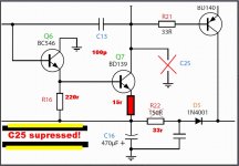
i would try to put a small capacitor - like 470p or so - in parallel to the 15R emitter resistor at Q7, to see what it does to sonics.
This resistance allows the base of the VAS to "move" voltage wise. This movement will be "transmitted" to the VAS output at the high frequency end through the millercap C13, so that the gain of the VAS cannot (in an idealised modell) go below 1 (0dB), thus "imparing" the compensation.
The said cap parallel to the 15R will ensure that VAS gain is able to roll off below 0dB. (if properly chosen in value, of course.)
Now, not having this cap can be good or bad - depends on the speed of the transistors, to put it simple.
If you don't face problems with stability without it, it's fine.
But who knows what the sonics will do. (I don't, thats the why of this post, actually 😉 )
So, I think the best way to find out, what it does, was to try.
Maybe sonics improve.
Also feel free to experiment with the value of the cap. If increased, it will influence lower and lower frequencies (then the influence goes the other direction, by the way, increasing the gain) and maybe start to have a real influence on loopgain in the audible range, and maybe bringing up the beloved highs.
use a good linear dielektric such as c0g, np0 or film/foil
regards,
krachkiste
Thank you Krachkiste
I am giving a break for a while.....next week will give a try,
regards,
Carlos
I am giving a break for a while.....next week will give a try,
regards,
Carlos
That BD139 was burned, previously, but because my supply producing strange signals
driving the amplifier to oscilation... after supply replacement by a 36 volts unit... was impossible to burn the BD139.
When using 44 volts, i was very near the transistor limits considering the max VCE, load was difficult too, low impedance (3.5 ohms), inductive as my resistance is constructed coiled and have metal core inside, and also i had more than 2uf in parallel with the resistance.
The introduction of 15 ohms resistance, or lower value, changed the reproduction signature, also was needed to cut a copper track....you can avoid that if you want.
Also, when i had the second VAS burned, also the first VAS had gone too...so... they are direct coupled.
No more transistors burned after the increase the first VAS colector load resistance to 220 ohms, having other capacitors removed/substitute made simultaneously.
BD139 is a 100 volts transistor in some datasheets, but i can remember it was specified as 80 volts transistor too, in other papers, so i am not sure if it is a 100 volts or 80 volts...using the 44V supply, them the peak to peak is dangerous to this transistor...shorted base to emitter (maybe because first VAS) and also shorted colector to emitter (maybe excess of swing).
Friends will come to listen.... and i will produce a board without modifications, will use the previous schematic, the Dx Blame ES...and will avoid difficult loads or extreme loud reproduction entering distortion... this will keep the ES safe...as it can play this way without problems... the amplifier, the ES, was alergic to difficult loads and very high containt of high frequencies clipping the amplifier...... the other amplifier, the second channel, will be the last schematic, and i will remove the 15 ohms resistance, because this way, keeping the resistance, no need to even compare..the new schematic will loose very easy...no chance to comparison.
Interesting...just that resistance changed the amplifier...not more shy bass....now the treble is shy... the Dx amplifier, the standard one, was not sensitive to these changes, i have included current sink in the differential, tried CCS in the differential, this two stage VAS...and i could not have the same result i had this time...there's a difference i am still wondering where is it.
There's an audible ratio i think... when you increase one, the other became shym (perceptive bass and trebles reproduction)...and this happens because you have listened the inverted sittuation before...so... the conclusion is because our mind was poluted...we really need fresh, brand new, without prejudice, evaluators to test.
I will try that capacitor, the ancient one, used in parallel with the emitter resistance..the one works increasing gain for AC, because it is a short to audio frequencies....it was used down the sixties, but to increase low frequency reproduction...usually they were microfarads units...will try, but next week..... for DC we go protected..but for AC, and that's our oscilating case, the introduction of capacitor will let the stage under danger i think.
regards,
Carlos
Last edited:
- Status
- Not open for further replies.
- Home
- Amplifiers
- Solid State
- Dx Blame ES .... based into the Blameless, i am trying a new amplifier