I am glad to receive news from you Ekkart.... good that your amplifier
Is working well and that you are making sucessfull experimentation with bias.
Thank you to inform what is going on with you.
regards,
Carlos
Is working well and that you are making sucessfull experimentation with bias.
Thank you to inform what is going on with you.
regards,
Carlos
A speaker fuse may add more distortion and bass colouration than any electrolytic capacitor. Resistance is signal dependent.
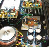
I will try to install the supply inside my enclosure..then i will manage to build an
electronic protection..delay insertion, DC detector and maybe overcurrent sensor....i will use something from Randy Slone book.... will build and test, naturally, then will let you know how it works and will post the schematic for your use.
Randy Slone - Electricity and Electronics - book page 278
regards,
Carlos
Last edited:
I could not feel difference..but will listen in my normal room and for longer time
Also i will invite my friends to come to evaluate, because i have my own position about voltage regulators (no good) and this may influence my decisions.
Others will evaluate for me..... then i will post results.
For a while, working fine, sound seems to be the same...but i was outside my normal audition room..and could not compare....we gonna see in the next exciting chapter (at least it is exciting for me)
regards,
Carlos
Dx Voltage regulator is good...it is huge..you can abuse
Don't you believe me?.....that's good...never believe...ask proofs.
I told we can have positive regulation..means the output voltage increases when you load..in the place to have voltage drops, you gonna have voltage increasings.
Here i am proving what i use to say:
YouTube - Electronic supply load test 5A
regards,
Carlos
A speaker fuse may add more distortion and bass colouration than any electrolytic capacitor. Resistance is signal dependent.
Nah... the cheapskate bean counters will put in a 220 uf.... maybe 470 if you're lucky. THAT will provide some bass coloration for ya.
Speaker fuses do indeded distort. Pro amps which use output crowbars put the fuse INSIDE the feedback for that reason.
Yeah!...that's the way i like it....the thread very funny, people with good mood
playing around...and of course i will contribute with this distortion story.
You see... fuse has a very thin wire..so, fat electrons when flows goes kicking side by side and disturb the electrons flow...some of then felt angry and decide to go back to the source..they do not want to play anymore..this way..we have distortions....maybe because wire without gain, and outside the feedback loop is capturing some microwaves from the universe black hole.
Really...the problem is that people does not use wire with gain.
ahahahaahahah!
🙂🙂🙂
Thank you, you are making me laugh.
regards,
Carlos
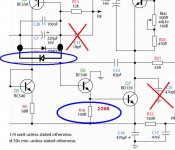
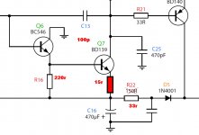
I have a suggestion to reduce power in this transistor
Increase R16 to 220 ohms, as this transistor is working warm when we keep the amplifier working under overdrive sittuation for long time...this is not healthy for this small transistor.....or...substitute the transistor by a BD139... leads will be a problem if you do this way....better to increase this resistance to reduce power from 250 miliwatts to almost 115 miliwatts (aprox.).... this transistor is a 500mW unit.
Thank you Wahab, you have already suggested that.
The "x" marked in red where already removed....but the extra diodo will be helpfull, despite reduces Q2 action.
I am playing, producing destructive tests to see how resistant the amplifier is.
regards,
Carlos
Attachments
Hi CarlosIncrease R16 to 220 ohms, as this transistor is working warm when we keep the amplifier working under overdrive sittuation for long time...
Perhaps you could put a resistor at the collector of Q6, to drop some voltage and share the power?
Regards - Godfrey
Hi Carlos
Perhaps you could put a resistor at the collector of Q6, to drop some voltage and share the power?
Regards - Godfrey
This idea work, godfrey, but then, this transistor s collector will see a signal appearing due to the transistor functionning in a common emitter mode.
So a capacitor should be added in paralel with this resistor to keep
the collector in ground in AC mode...
I am trying to destruct the amplifier... i want to have absolutelly sure it will be
not only excelent in sonics, but also understructable.
So, i was very bad this morning....and i could destroy the second VAS!...yessss!.
What i have made...increased supply voltage to 45 plus 45 volts..hehehehehhe... watch BD139 specifications!.... then i have installed 3.5 ohms load at the outpuit, an inductive load..the one i have, the 70 watts big gray one..in parallel i have installed 2.2uf/450 capacitor....in parallel with the load... input signal was 200 kilohertz, 4 volts peak to peak, saturating the amplifier.... the BD139 gone....Paft!..ploft ...pow!
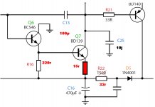
Then i made these modifications you see in the sketch..... then this transistor have not burned anymore...observe rail resistances, both positive and negative are reduce to 39 ohms, to avoid non symetrical clipping.... 15 ohms resistance in the second VAS, the BD139 emitter...increase (TKS Wahab) the first VAS emitter resistance (load to that transistor)...the capacitor was modified, the Miller one, in the last update and upgrade made.
I will go back to the Dx Corporation Torture room.... to try to kill using other ways.
These modifications turns the amplifier animal proof...crazy monster proof..against all specimens we have in our zoological nature...
ahahahahahah!
regards,
Carlos
not only excelent in sonics, but also understructable.
So, i was very bad this morning....and i could destroy the second VAS!...yessss!.
What i have made...increased supply voltage to 45 plus 45 volts..hehehehehhe... watch BD139 specifications!.... then i have installed 3.5 ohms load at the outpuit, an inductive load..the one i have, the 70 watts big gray one..in parallel i have installed 2.2uf/450 capacitor....in parallel with the load... input signal was 200 kilohertz, 4 volts peak to peak, saturating the amplifier.... the BD139 gone....Paft!..ploft ...pow!
Then i made these modifications you see in the sketch..... then this transistor have not burned anymore...observe rail resistances, both positive and negative are reduce to 39 ohms, to avoid non symetrical clipping.... 15 ohms resistance in the second VAS, the BD139 emitter...increase (TKS Wahab) the first VAS emitter resistance (load to that transistor)...the capacitor was modified, the Miller one, in the last update and upgrade made.
I will go back to the Dx Corporation Torture room.... to try to kill using other ways.
These modifications turns the amplifier animal proof...crazy monster proof..against all specimens we have in our zoological nature...
ahahahahahah!
regards,
Carlos
Attachments
😀I told we can have positive regulation..means the output voltage increases when you load..in the place to have voltage drops, you gonna have voltage increasings.
Do you think that resistor in the colector is needed?
explain your reasons Godfrey, then i will be motivated to try.
Do you mean to share current in the both circuits?... input (BE) and output (CE)?
thank you,
regards,
Carlos
explain your reasons Godfrey, then i will be motivated to try.
Do you mean to share current in the both circuits?... input (BE) and output (CE)?
thank you,
regards,
Carlos
explain your reasons Godfrey, then i will be motivated to try.
Do you mean to share current in the both circuits?... input (BE) and output (CE)?
thank you,
regards,
Carlos
It s a way of protecting this transistors from excessive
currents.
But since you did add a resistor to the emitter of the Vas,
you just have to add a zener of about 3.6V from base of
the bc546 to negative rail...
This way, the peaks current will be limited to
(3.6 - 0.6)/220R for the bc546, thats about 13mA.
And the Vas will see a max of (3.6 - 1.2)/15R , that is, 160mA
of max peak collector current..
Of course, these kind of currents limiting should not alter the perfs,
but in fact, are needed only if the amp is to be used in
extremely difficult conditions, as PUBLIC ADRESS systems
rolling at full volumes all night with difficult loads.
Hi Carlosexplain your reasons Godfrey, then i will be motivated to try.
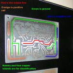
I show the ideas with pictures (always the best way for me 🙂)
There were two reasons for my idea:
1) When the amplifier is used normally, there is voltage across the extra resistor (I chose 3K3, it can be different), so there is some power wasted in the resistor, but less power in the transistor (Q6) so it will be cooler. With the bigger resistor, now 220R instead of 100R, maybe this is not a problem anymore?
2) When the amplifier is driven too hard - when the output clips to the negative rail, then the input stage can put about 4mA into the base of Q6.
In the old circuit this will make a very big current through Q6 into the base of Q7 - maybe 100mA or more. I think Q7, the BD139, will be OK but it may be too much for Q6, the BC546 - I worried that this one might burn.
With the extra resistor, Q6 is safe - current can only be up to about 10mA - then all the voltage is across the resistor and Q6 will saturate.
Wahab is right, though. For normal use, there will be voltage swing on the Q6 collector. Perhaps this will affect the sound? I don't know.
Now I think Wahab's idea is better. For normal use, the zener has no effect - it does not conduct. Only when the amplifier is clipping it has an effect - to make sure the voltage at Q6 base can not go too high, so current will not be too high and burn the transistor.
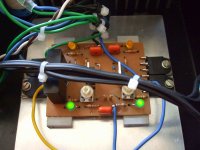
I drew Wahab's idea with two LEDs instead of the zener. This way there will be flashing lights when the amplifier is clipping - a warning to turn down the volume! 😀
Regards - Godfrey
Attachments
Reinventing wheel, gentlemen?😛
http://www.diyaudio.com/forums/solid-state/160061-slones-11-4-blameless-7.html#post2072563
It is very old idea, in many books and schematics. And capacitive loading VAS with 470pF to GND is very suboptimal way to stabilize amplifier- loading means increased distortion at higher frequencies.
http://www.diyaudio.com/forums/solid-state/160061-slones-11-4-blameless-7.html#post2072563
It is very old idea, in many books and schematics. And capacitive loading VAS with 470pF to GND is very suboptimal way to stabilize amplifier- loading means increased distortion at higher frequencies.
Last edited:
Very much appreciate your efforts folks...genuine experts addicted to help in advance
to others intentions (if exists in your cases).
Very clear and helpfull explantions from Wahab and Godfrey...i do respect people alike you, doing things to help, not only telling us to do this or that....explaining in details it is much better, as i will learn things i don't or will confirm things i already knew and all readers have the advantage of your clear explanations.
Thank you very much Godfrey and Wahab....soon i will test this....maybe even today if i manage to repair my television in advance.
regards,
Carlos
- Status
- Not open for further replies.
- Home
- Amplifiers
- Solid State
- Dx Blame ES .... based into the Blameless, i am trying a new amplifier