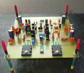
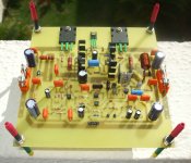
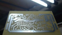
Well, i have finished, the Dx Blame ES assembled into the official boards
is almost ready to go.
You may see the output transistors are not connected, this is because i have no " L " adaptor free to use, so, i will run wires from the board to an external heatsink that has already power transistors and insulators.
Resistance from positive to ground and negative to ground is very high, this means no problems, the amplifier will operate at the first moment it will be switched on.
In a couple of days i will be listening, i am busy with other things to do, so, will do that slowly.
Transistors, these rarities, are there for decoration purpose only, it was saved from a dismounted CNC machine.
regards,
Carlos
Attachments

Last edited:
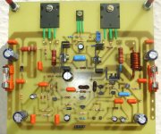
Do not install metalic resistance inside the coil
You can see i did that, but was just to produce a picture.
During real operation, the resistance will be cutted out because my coil is enought and i do not need to spred the bandwidth blending the coil that way.
The good friend made this way and asked me to install inside, then i did it to make him happy, but this is not a good technicall solution and i suggest you dear friends, not to do that way.
Metalic parts, iside coils, when current is high crossing the coil, then saturates magnetically the coil core metalic parts (resistance), and this produces annoying noises superimposed to the audio waveform...happens during high current peaks only.
regards,
Carlos
Wanna be happy?
Join the Dx Corporation.
Excelence in amplifiers and happyness guaranteed.
Dx Corporation is from the Samba Country:
YouTube - Dx Amp - Brasil, electronics & Samba
Join the Dx Corporation.
Excelence in amplifiers and happyness guaranteed.
Dx Corporation is from the Samba Country:
YouTube - Dx Amp - Brasil, electronics & Samba
Dx Corporation exists only in my dreams, we are just a group of friends that use to
cooperate, to help one each other.
Since the early beginning of Dx amplifiers, i had, and i still have, several folks helping a lot, producing boards, layouts, schematic, suggestions and support.
Klaas Veenstra - Holland
Nico Daneel - South Africa
Daniel Mustran - Croátia
RAJ - Malaysia
Greg Erskine - Australia
Todd Johnson (taj) - Canadá
Alexmm - Rumania
Counsellors, Council, technical advisers, audio Gurús were Hugh Dean and Graham Maynard.... Eva has helped also, but more recently.
Safety department, law support, the lovely Xeriff, our Marshall, my dear best moderator Carl Weldon, with his double barreled shot gun, fast responsive man, a fair and very good man, he made the thread safe, has keept the place respectable with his, active, precise, super fair and very strong presence... some tried to enter to make mess, to destroy, they have faced a lot of smoke, shot gun pellets and salt grains in their back bumpers!..... ahahahahahah!
Well, these ones were the ones more present, in the past and some strong and tireless are present now a days, there are several more that helped a lot, and all Dx builders bellongs to the Corporation as Crew men, and they have virtual pictures in the Dx Corporation Headquarters hall of fame, a Gallery having the Dx builders.
They are around the world, in all Continents, and they talk several languages, the common thing we have, our connection, is the passion by audio.
These ones have helped with instruments, software, boards and parts:
Hugh Dean
Todd Johnson
Renato Comerlatte
Hugo Camara Schultz
Sergio Vaz
Dudainc
Sakis Petropoulos
Greg Erskine
Nico Daneel
Raj
Klaas Veenstra
Marcisio Souza
Rudi Rozek
Anonimous
Soon i will make a video, there i will try to collect all names, pictures and countries from the corporation members, as also the amplifiers produced in pictures,but this takes time, thread is enormous, and my search there is just starting.
I will apologize, in advance, to the ones i forgot in the upper list, and as soon i remember i will produce new list of main cooperators, main helping hands i have received.
Corporation targed is "Audio Excellence to make you happy!", and we want one Dx amplifier in each home, and this around the world..hehehe..we want a little bit too much isnt'it?
Next month, in Dubai, in the highest tower floor, we gonna have a celebration of Dx Corporation 7 years of activity, with the Golden Shot Gun prize to the hands of Carl Weldon (a virtual meeting)
regards,
Carlos
Attachments


Last edited:

Brasil is not only the Dx Corporation country, it is also the place where
you may find 80 millions of Amelias.
YouTube - Dx Amp - Brasil, electronics & Samba
Holland (Dutch), Germans, and other Europeans land here to have fun, they never returned, they found their Amelia and they are living happy with us.
If you understand a little bit of German, listen what a German said about us:
YouTube - Dieter the happy Kraut!.avi
regards,
Carlos
My dear Carlos,
As usual you give me so much credit for so little work. We really must remember that the moderators are a team and that decisions of action are decided in the 'backroom' among us. Having said that, I thank you for your praise. It is nice to know that someone thinks we are doing a good job. That's not always the case as you know.
Now can I ask Uncle Charlie a favour? Can you spell my name without an 'R' please? 😀
Thank you,
Your friend Cal
Yes Cal, moderators team, .... you all, as a team, decide together.
But you will continue to be my prefered moderator, as you were present in many important times and i have a very good memory about that.
Maybe the hours i am active may be your time to be active too.
Thank you all, thanks for the team by the excellent job, in special because you all avoid to make non necessary intervenctions, respecting our freedom to exercise our self criticism.
A very special thanks to you.
your friend,
Carlos
Last edited:
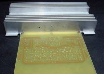
My people (brazilians) are building, some of them are trying better images
to produce layout, other is studying the photo chemical image transference method, the one uses light and transparency, light projected into the copper board, previously covered with photo sensitive material.
One of them transfered the pdf layout image to the photoshop program, then have increased the image size (pixels) to avoid the digital defect we have, triangle or square shape at corners...now you can zoom in the image and will never see defects.
heheheh, image resulted in 5 Megapixels, a little bit big.... solution not very good.
Well, while trying they are learning themselves and teaching me different ways to use other chemical to etch copper boards.
We are trying a mix of Hydrogen peroxide and muriatic acid... this boils when touching the copper, alike the stomach medicine, Andrews Salt or Alka Seltzer, and those things...boils spelling gazes and "eats" the copper very fast.
This way we do not have to go downtown to buy the dark chemica, thatl grainy and dirty material we often use (Iron perchlorate), we can buy Muriatic in nearby shops of construction materials because it is used for cleaning purposes, to remove paint and so on.... the Hydrogen peroxide is used to women (and surfers too) hair to make them blond (agua oxigenada...water with oxigen), so, we can buy in nearby drug stores.
Surfers use, here, this chemical and paraffin, these products, exposed to the sunlight changes the hair colour from brown to yellow, fake blond... this way they feel themselves alike Californian Surfers.
regards,
Carlos
Attachments

Last edited:


dx blameless
dear sir
greetings still trying to find fault the 150 ohms in negative supply rail
becomes hot voltage after resistor drops to 6 volts something is shorting any
clue or should make new pcb one in last post advise me desperate to make
dx blameless
thanking you
andrew lebon
dear sir
greetings still trying to find fault the 150 ohms in negative supply rail
becomes hot voltage after resistor drops to 6 volts something is shorting any
clue or should make new pcb one in last post advise me desperate to make
dx blameless
thanking you
andrew lebon
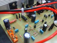
I have a friend that has faced the same problems, was not the layout version 1.4C
In his case, not only the board layout had problems, but he has inverted a lot of transistors.
Also he had tried a wrong method to find mistakes, he was removing transistors one by one, this old style does not works fine with direct coupling stages, he burned more parts doing this way.
He had this negative rail resistance overheating.... he gave up from the old board and he is preparing the new board version, the last update and upgraded board, the one no one has found mistakes till this moment.
I have not powered on this new board, as i am a hell busy with plumbing troubles in my home.... soon i will be 100 percent sure the board is perfect.
Brazilians have build in several board versions and they go fixing boards following the posts published about bugs found, i did twice but using my own board style, so, we have not the board tested yet.
BC556/546 has the base in the middle, it is different from 2N5401/5551, some people confuse this, also we had this wrong in some boards too, wrong in the pcboard layout.
BD139 is strange also, the metalic part facing you, legs down, then from left to right you have base, colector and emitter.
The electronic circuit was tested several times, no problems known about the circuit.... we are having board layout troubles (we had in early past) and human mistakes, and these, dear Andrew, is a constant, happens daily, with everybody and everywhere.
Hard work is what you have to do, i will search for the debugging method i have made to Masterinvi, published in the DHR Turbo thread and will post is here too, in order to help you.
I am sorry you're facing troubles, feeling frustrated and sad, this is normal, but the glad moments you will live when this wonderfull sonic machine start to work will make you forget all bad moments you had and will make you feel very happy with the travell into the world of pure sound.
There's an stupid, stone age method some guys use... if that resistance is hot, or burning, as 40 mA is crossing it, and this means 240 miliwatts, then they install 1 or 2 watts resistance in the place, after that they search for hot parts in the input, the differential, because if this current is overheating the resistance, may overheat also the part inverted/damaged/shorted or something alike... the stone age method sometimes shows you the faulting part touching with your fingers, and then observing schematic you may realise what is going on.
regards,
Carlos
Attachments

Last edited:
I will post three texts in sequence, they may be helpfull for debugging, there are
some tips and tricks:
How to check circuits - 1
First thing to be done is to check the board, because when we prepare the board, or when we etch at home, them you may have failures, copper lines missed, and during soldering you may have shorts.
So, prepare a schematic copy, a printed schematic and a colour pencil or pen and go watching the board througth strong ligth, put a ligth bulb bellow the board and go inspecting traces and go painting each one of them in your schematic, till you have painted all schematic, trace lines covering or parallel and very near the schematic connection lines... doing this you will find missed lines, shorted lines and interrupted (broken) lines.
Solder once again each solder point, melt the solder and add a little bit of new solder, if you face bubbles in the solder point, there's a bad solder, a problem you may have fixed soldering these points once again.
Then, having all connections removed, as input cable, output cable, positive rail wire, negative rail wire and ground (VBE multiplier too) them measure resistance to search for semiconductors, or transistors shorted, line shorted that you could not discover with visual inspection...measure resistance, high scale, 2 Mega or 20 Mega, you may be patient to wait the meter reading, it will charge electrolitic condensers and will having strange numbers floating, depending the polarity, resistance may reduce to zero and them increase again till will be stable reading several kilo ohms, more than 30K, usually you have more than 500K when everything is all rigth.
Do that from positive to ground, and them invert your multimeter probe tips and measure once again.... register the numbers in a piece of paper, make your notes about the resistances you have found.
Do that now from negative to ground and them invert your multimeter probe tips once again, take notes from the values you have,
Now check from positive to negative and invert your multimeter probe points.
How to search for errors, part 2
How to check circuits - 2
...then go removing transistors, one by one, do not remove all them, go one by one, and you will find the shorted one... them replace that one and continue, you may have other, or others.
Doing that you must check if you are using the correct transistor, and you may check in the internet the transistor leads, the base lead, the colector lead and emitter lead, you should download data sheet and watch this carefull, also check three times if you are using a NPN in a place you need a NPN and if you are using a PNP in a place you need PNP....so , transistor will be checked...also you will find fake ones, there are NPN fakes that measure alike PNP.... yes...happened this week with a friend of me!.
Check all transistors.... short remains?... then check if output transistor case is insulated related the heatsink, the output transistor's colectors cannot show resistance to the heatsink, heatsink is usually grounded, a wire must go from a heatsink screw (soldered) to the transformer secondary coil center tap pin, the traditional grounding system.... your colector can be shorted with the heatsink, you have already checked all transistors disconnected (out from the board) so, you know they are fine.
Now electrolitic condensers, remove them and check them, also check if you have installed them in the correct polarity and check the value you have used.
Now check resistances, each one of them, go painting into the schematic each one you lift one side to measure..let one side soldered and measure, this way you will not have the circuit fooling you... take this chance to check values with your multimeter, check value comparing with the schematic value.
Doing that, is almost impossible to remain a failure...but it is hard work, do not engage your brain, it is hard, mechanicall, automatic work, to desolder, to remove parts, to take notes, to measure, and to return to the board, one by one.
This is what i can do to help you..do not waste your time trying to analise why negative rail is having so big power consumption, go measuring and you will find your mistake..measure everything, all capacitors, all condensers, all resistances, all diodes and all transistors..check trimpot, vbe multipler, supply voltages, supply rectifiers and so on.
Be happy, good luck!
Measurements, power tests, input signal generators, power amplifiers
Measurements, debugging, test signals for power amplifiers
The multimeters, the digital ones, have precision only if you are measuring sinusoidal waveshape and 60 hertz, your mains frequency....out from this frequency range, 40 to 200 hertz, the meter is not precise.
So, to measure power, first you need a load and a sinusoidal low distortion generator entering the amplifier input terminals, also you need an Oscilloscope to watch when the amplifier starts to clip, of course you may perceive the sonic differences using your ears. but when ears detect, the scope have already detected earlier and your detection is really a square wave, not the clipping threshold but much more clipped than the level we use to measure that is a very small clipping.
Measuring music playing, well, frequencies are not sinus, the frequencies are not the ones your meter can measure with precision...also if you evaluate sound with a speaker itself, outside the enclosure, it will not play loud or impressive, even if the unit is almost hitting the back end you will feel it is not strong.
The DHR turbo, for example was made to dissipate enormous power in the load, not in the heatsinks, as it is not a Class A amplifier, when iddle it is dead cold, will be very hot when the heatsink is too small of if your power output is very high, also if you stand by current is wrong and too much high, i repeat, better to check 1 miliampere each power transistor, of course you can go to 15 miliamperes, but this means more heat together more waste of power and i doubt the advantage of it. The DHR turbo, for instance, was made for power, audio quality was secondary, was an accident that also the audio quality resulted good, the target was power!
It can be transformed into a killing beast if you increase the driver's transistors iddle current to 40 miliamperes, but they must be into the main heatsink and you must reduce the floating emitter resistance a lot.... a killing beast, so killing that may be able to kill itself.
Using scope you measure the peak voltage and 70 percent of this may be your rms output voltage.... them multiply by itself (squared) and divide by your speaker impedance.... yes, you know that, but some reader does not know.
For instance, if you read 8 volts...then multiply 8 volts by itself, means 64 as result, then divide by the speaker impedance, let's say 8 ohms, result is 8 watts.
Normal electronic multimeters, in the AC scale, are able to measure, with precision, the mains frequency, so, 50 or 60 hertz is the frequency you may have precision, use this frequency to test, search for a small transformer, these one have 4, 6, or 10 volts alternated, then install a 100K trimpot in two of the secondary wires...pick the central lead and one of the extreme lead that will be your ground...now you have a sinusoidal, 50 or 60 hertz, signal generator, adjust the trimpot to measure from 750 milivolts to 1 volts and then plug this signal to your power amplifier (Dx power amplifiers works with this voltage in the input to give you full output power)
When we measure using analogic meters, well, we have balistics, the pointer weigth, the measurement use not to be very good, we need stand sinusoidal signal and the frequency must be the one your meter has precision.
Amplifiers alike the DHR Turbo, even with bad supplies must go to, at least, 150 watts
Transformers that use bimetal inside the secondary or primary coil, they do that for protection, bimetal when over heated switch off the circuit, a thermal protection, but, sometimes this shows enormous series resistances that kills the transformer output voltage stability, reduces a lot the transformer power because of series resistance...these transformers, or other defective transformers, have enormous drop of voltage when you suck energy from them.
There's no possible magic, power amplifier produces audio power if the supply can manage to send power to the amplifier, weak supplies will never produce high power, we need huge transformers, squared monster measuring 20 centimeters each side if E/I type to obtain 600 to 1 Kilowatt of power in a single channel... a lot of transistors cannot do that, we need huge electrolitic condensers filtering and enormous transformers, and the transformer power must be, at least, 60 percent bigger than your expected output power, say, to 1 Kilowatt of audio you nead 1.6 Kilowatt transformer. (Class AB)
Last edited:

Congratulations, I'm seeing progress. The layout is electrically ugly but it's pretty to the eye 😉
The Spanish judge renders her verdict. 😛
So, how can the layout be improved (electrically), Eva? Teach me please (for future reference).
..Todd
- Status
- Not open for further replies.
- Home
- Amplifiers
- Solid State
- Dx Blame ES .... based into the Blameless, i am trying a new amplifier