Hi Frank,
Your power supply does not fulfill the requirements. The Najda wants +5V and a pair +12V/-12V, meanwhile your supply delivers only +5V and +12V.
On top of that, it seems that you have short-circuited GND and -12V input on Najda.
If you don't supply -12V, then the sound will be distorted because the negative part of the audio waveform will be shaved off at the volume chip level.
The part that you have seen frying is the input inductance. With the neighboring capacitor, it forms a HF filter. If you can still connect, this means that the inductance is now short-circuited, which is alright. I can send you a replacement part but in the meantime it seems that you can still use your Najda board if you get an appropriate power supply.
A model of supply that's been tested is this model.
Please stop using the Najda board until you get the proper power supply otherwise you might damage it even more.
Any question, please let me know.
Nick
I've seen the link to the recommended power supply which is helpful. Are there recommended parts and links for the other equipment for a noob like me?
Also, I am interested in the noise and distortion specs. Is this information posted somewhere?
Thanks
Also, I am interested in the noise and distortion specs. Is this information posted somewhere?
Thanks
Are there recommended parts and links for the other equipment for a noob like me?
I have a complete front board kit now that includes all the parts you could need for a sleek user interface.
Please see the details here.
Cheers
Nick
Question: Can Najda display the digital input signal bit and sample rate somehow?
Be cool to see that it really is working at 24/96, 192 etc.
Be cool to see that it really is working at 24/96, 192 etc.
Last edited:
Hi there,
Today I received my new Najda board. After a few difficulties, I was finally able to listen to music. With rephase I created the fir filter, and the result is very good. Definitely better than a separation according LeCleach. As well as I did not imagine the sound. One question I have. Where do I replace the opamps on the board. The OPA 627 AP can I use? Thank you in advance.
greeting
frank
Question: Can Najda display the digital input signal bit and sample rate somehow?
Be cool to see that it really is working at 24/96, 192 etc.
The internal sampling frequency is displayed in the status bar when you connect with NUC.
The digital input sample rate and bit depth are not available. You don't really need to know that because the signals are going across the sample rate converter. The internal sample rate is more meaningful.
Hi there,
Today I received my new Najda board. After a few difficulties, I was finally able to listen to music. With rephase I created the fir filter, and the result is very good. Definitely better than a separation according LeCleach. As well as I did not imagine the sound. One question I have. Where do I replace the opamps on the board. The OPA 627 AP can I use? Thank you in advance.
greeting
frank
Congrats Frank!
Where's the pic? 😉
Opamps are mounted on sockets, as you must have seen. The 2 ones on top are for the analogue input. The 4 ones below are for the outputs.
I think you could use the OPA627, no problem. However, I wouldn't do that immediately. The benefit of swapping opamps for another model is indeed rather subtle, as it's been reported here and elsewhere on various occasions.
Thanks Nick - It's good to be able to check the bit and sample rates as music server SW can sometimes not do what it should.
I'm getting a WaveIO USB -> I2S board and that has LED for the various sample rates. I will make these visible on my Najda case somewhere so I can see what's what😉
I'm getting a WaveIO USB -> I2S board and that has LED for the various sample rates. I will make these visible on my Najda case somewhere so I can see what's what😉
Hi Speedysteve7,
I've also ordered one to Lucian few days ago 🙂
I'm getting a WaveIO USB -> I2S board
I've also ordered one to Lucian few days ago 🙂
Rear panel design example
Further to frequent demand, here's a mechanical file for a rear panel.
The file format is FPD (Front Panel Designer) and is intended to be used with the application made available by Schaeffer (in Germany) or Front Panel Express (in the US).
You can get this file, modify it by adding and/or removing elements, then order your own panel. I've prototyped the file so you should not expect any issue (if you don't introduce your own mistakes in the design ... 😉).
Here's the basic data of the intended box:
- 1U case 438 x 42 mm (W x H)
- The PCB should sit at a height of 6.5 mm (in my design, that's 2.5 mm bottom plate width and 4 mm spacers).
- On the far left, there are cutouts for a rocker switch and a power socket. You should adapt these cutouts for the parts you have selected.
- On the far right, there are cutouts for the expansion board. You should delete them if you don't intend to install the expansion board.
- You might want to add a cutout for a USB plug if you're using a USB/I2S converter and possibly other things.
I'll post pictures of the real thing soon.
Cheers 🙂
Nick
Hello,
Hereby I submit a few photos after.
Temporary construction with new Op amps LME49720NA:

The LR24-filters are created with the software rephase. The eq-function I have also performed with rephase by use the Input processing of NUC.


Here are some pictures of my system:
NAD325BEE for the bass and Harmann-Kardon AV Receiver with separable output stages for the rest 3-ways.

And last but not least the diy-speakers Visaton Atlas MK V

The measured frequency response with Arta:

Hereby I submit a few photos after.
Temporary construction with new Op amps LME49720NA:
The LR24-filters are created with the software rephase. The eq-function I have also performed with rephase by use the Input processing of NUC.
Here are some pictures of my system:
NAD325BEE for the bass and Harmann-Kardon AV Receiver with separable output stages for the rest 3-ways.
And last but not least the diy-speakers Visaton Atlas MK V
The measured frequency response with Arta:
Attachments
Last edited:
Hi all!
Today I put my Najda on its place in my stereo system. Now it's running as a 2-way xover.
Now some questions for Nick and others
1. Is it any capacitor in series between output OP amp and output connector?
2. Why some time I have strong distortions with clipping using SPDIF coax input from my Rega Jupiter CDP?
Temporary construction with new Op amps LME49720NA:
View attachment 431749
Hi Frank,
Thanks for posting! Hope that this is temporary indeed 😉
The measured frequency response with Arta:
View attachment 431758
Nice! Can you post the frequency response of the filters? Just curious.
---
Hi Mike!
1. Is it any capacitor in series between output OP amp and output connector?
Yes. 22 uF TH located between OPs and volume chip.
2. Why some time I have strong distortions with clipping using SPDIF coax input from my Rega Jupiter CDP?
Most probably not enough headroom. Please post more details about your setup.
---
Cheers
Nick
Most probably not enough headroom. Please post more details about your setup.
---
Cheers
Nick
Hi Nick! I have 3 sources - two Digital an one Analog. Digitals are CDP Rega Jupiter (connected to Najda via coax SPDIF) and HTPC with JRiver 19 and RME HDSPe AIO as an output device (connected to Najda via optical SPDIF). In HTPC I can reduce output level in RME's HDSP Mixer, but in CDP I can't. I set -6dB on Input Processing and -6 dB on Chennel Processing, but I have to set +12dB in the output. In this case I have Volume -6dB for comfort listening. The analog outs going to Yamaha P5000S amp (below 150 Hz) and to tube monoblocks amp for MF and HF.
Hello,
the frequency response of the filters is carried out with rephase:
Fir-Filter for bass (Chassis Visaton TIW 300)

Fir-Filter for mid1 (Chassis Visaton AL 170)

Fir-Filter for mid2 (Chassis Tang Band W4-1320SIF)

Fir-Filter for high (Chassis Vifa XT 300 K/4)

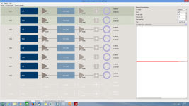
The filters in NUC:

Electrical Sum in NUC:

Electrical Sum include Delay/Phase in NUC :

I am very satisfied with the sound. I just have not managed to get it to run the display. I do not know exactly where is located on the control board pin 16.

Thanks
Frank
the frequency response of the filters is carried out with rephase:
Fir-Filter for bass (Chassis Visaton TIW 300)
Fir-Filter for mid1 (Chassis Visaton AL 170)
Fir-Filter for mid2 (Chassis Tang Band W4-1320SIF)
Fir-Filter for high (Chassis Vifa XT 300 K/4)
The filters in NUC:
Electrical Sum in NUC:
Electrical Sum include Delay/Phase in NUC :
I am very satisfied with the sound. I just have not managed to get it to run the display. I do not know exactly where is located on the control board pin 16.
Thanks
Frank
Hi Nick! I have 3 sources - two Digital an one Analog. Digitals are CDP Rega Jupiter (connected to Najda via coax SPDIF) and HTPC with JRiver 19 and RME HDSPe AIO as an output device (connected to Najda via optical SPDIF). In HTPC I can reduce output level in RME's HDSP Mixer, but in CDP I can't. I set -6dB on Input Processing and -6 dB on Chennel Processing, but I have to set +12dB in the output. In this case I have Volume -6dB for comfort listening. The analog outs going to Yamaha P5000S amp (below 150 Hz) and to tube monoblocks amp for MF and HF.
Mike, please post screenshots of your settings in NUC. Don't set headroom at the source level.
Hello,
the frequency response of the filters is carried out with rephase:
Fir-Filter for bass (Chassis Visaton TIW 300)
View attachment 432076
Fir-Filter for mid1 (Chassis Visaton AL 170)
View attachment 432078
Fir-Filter for mid2 (Chassis Tang Band W4-1320SIF)
View attachment 432079
Fir-Filter for high (Chassis Vifa XT 300 K/4)
View attachment 432077
The filters in NUC:
View attachment 432074
Electrical Sum in NUC:
View attachment 432075
Electrical Sum include Delay/Phase in NUC :
View attachment 432081
I am very satisfied with the sound. I just have not managed to get it to run the display. I do not know exactly where is located on the control board pin 16.
View attachment 432083
Thanks
Frank
That's very nice! You might have room for improvement by setting proper delays required by FIR filter of different lengths. Please see this post if it can help.
Re. pin 16 of the display port, that's indeed the one you have circled on the diagram.
Mike, please post screenshots of your settings in NUC. Don't set headroom at the source level.
That's very nice! You might have room for improvement by setting proper delays required by FIR filter of different lengths. Please see this post if it can help.
Re. pin 16 of the display port, that's indeed the one you have circled on the diagram.
The delays are already implemented. The bass requires 512 samples and the remaining 256 samples. The delay is thus 5.333 ms.
Thanks for the quick reply in connection with my display. Unfortunately, it still does not work. Do I need to completely reinstall the control board (LEDs, resistors, etc.). Can I order accessories necessary with a new control board?
Mike, please post screenshots of your settings in NUC. Don't set headroom at the source level.
OK, I'll do it tomorrow. How to reduce LED's brightness? Еspecially green LED irritates me 🙂
- Home
- Source & Line
- Digital Line Level
- DSP Xover project (part 2)