Hi dreamth,
You could use local regulation like Nakamichi did. They used transistors to send the ground current of the regulator to the opposite rail before the other regulator. This reduced injected noise by the beta of the transistor used.
Pretty darned smart if you ask me.
-Chris
You could use local regulation like Nakamichi did. They used transistors to send the ground current of the regulator to the opposite rail before the other regulator. This reduced injected noise by the beta of the transistor used.
Pretty darned smart if you ask me.
-Chris
Well worth it IMHO if you're powering a discrete low-level amp. But some of these applications are power rails for op-amps that already have 60 - 80+ dB PSRR at audio frequencies. I'm sorry, but I don't think a few microVolts of rail noise are worth bothering about in that case.
Best Regards,
Rick
Best Regards,
Rick
Last edited:
I had 2 CR4...but bx300 was the smartest of them all .Hi dreamth,
You could use local regulation like Nakamichi did. They used transistors to send the ground current of the regulator to the opposite rail before the other regulator. This reduced injected noise by the beta of the transistor used.
Pretty darned smart if you ask me.
-Chris
Attachments

Hi Rick,
Sometimes it does matter, even when you think it may not. That suggestion certainly isn't expensive or too complicated to do yourself. That and power lines tend to have currents and voltages from other stages that only show up when the system is processing a signal. So it isn't just the static mV worth of supply noise you're worrying about.
-Chris
Neat, they're basically exploiting opamp CMRR by cap-coupling the +in to V+. Roughly 40 dB more PSRR at the cost of two inexpensive components per channel? Count me in. That's one to remember for whenever you have a singleton input low-noise preamp like that.I had 2 CR4...but bx300 was the smartest of them all .
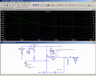
(Simulation attached.)
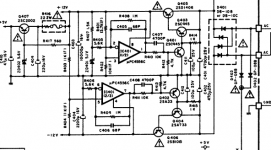
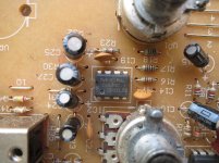
I can't say I get their +/-12V regs though.
Why didn't they bother to filter ZD401 when they did do the same for the +6V reference? Also, it seems like C411/412 would be making the regs rather slow, hence possibly why they have a boatload of capacitance on the outputs.
Attachments
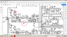
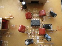
both inputs of IC401-1 see the same noise so it's canceled at the output as in their PB input stage.IC301 is in unity gain so very poor psrr and cmrr already...
You're right, it's not that fast as i advertised it.I didn't analyze that circuit in depth.
I think that those c411-412 caps stayed there as a legacy form the more advanced models where they needed a high power, high hfe buffer to preserve the 4556(otherwise powerful enough) slew rate when driving two pairs of transistors in parallel.C407 speed it up a bit. It looks a bit oversized though.
On the other hand q401-402 need to have a steady voltage under input transients and the 100uf is charged through 1kohm and discharged through some mohms of the 2sc945 transistor so maybe it's not that slow either...it's fast at cutting the q403 current so that the output voltage won't rise dangerously, it's slower at charging q403 base when the input go low so its main purpose is to protect the output and keep enough current in those capacitors.
c401/r414/c411 is also a filter so that when there's not much action the output is fairly now noise too.
I'd say this regulator is a philosophy in itself...
Attachments
-v please 😕both inputs of IC401-1 see the same noise so it's canceled at the output as in their PB input stage.IC301 is in unity gain so very poor psrr and cmrr already...
I have no idea what IC301 being a unity gain buffer for the zener-derived +6V reference has to do with PSRR and CMRR being poor.
Did you mean IC101 rather than IC401? Or IC302 which I was referring to earlier? IC401 is in the power supply.
If you did mean IC101 1/2, well yes, that is correct. Not only there but in fact almost the entire circuit, as +6V serves as the reference all over the place (this is commonly referred to as an "active ground"). I guess they may have done it because the NE652 needed it, otherwise much of the circuit with its +/-12 V split power supply would have worked just as well with a dedicated ground connection instead. (Typically Japanese, they like doing things a bit more convoluted than necessary.)
"Ground" always is an arbitrarily chosen potential. You say this is your reference and that's it. If your circuit is operating between +12V and +6V, you may just as well treat it as if it were running between +(12-6) V = +6 V (eff) and 0 V, with the +6 V (eff) supply bearing the noise of +(12-6) V. The circuit will not care one bit about any potential shared between +12V and +6V relative to "real ground", including noise. It's like a firmly attached camera inside a ship looking at an artificially lit internal room where everything is locked down - it will look the exact same no matter whether there is a storm raging outside or the sea is calm.
I exploited this in my simulation, since that conveniently also provided an ideal opamp which does not require any supply connections (the opamp only needed to be there and have approximately the small-signal bandwidth of a TL072, otherwise it was essentially irrelevant when it comes to demonstrating the effect since just about any half-decent opamp would provide enough CMRR).
I think the cd4066 , 4051, 4052...needed that half voltage too...i won't go back to that schematic.I thought high psrr and cmrr come with higher gain...which isn't the case with the unity gain circuit...-v please 😕
I have no idea what IC301 being a unity gain buffer for the zener-derived +6V reference has to do with PSRR and CMRR being poor.
Did you mean IC101 rather than IC401? Or IC302 which I was referring to earlier? IC401 is in the power supply.
If you did mean IC101 1/2, well yes, that is correct. Not only there but in fact almost the entire circuit, as +6V serves as the reference all over the place (this is commonly referred to as an "active ground"). I guess they may have done it because the NE652 needed it, otherwise much of the circuit with its +/-12 V split power supply would have worked just as well with a dedicated ground connection instead. (Typically Japanese, they like doing things a bit more convoluted than necessary.)
Also, it seems like C411/412 would be making the regs rather slow, hence possibly why they have a boatload of capacitance on the outputs.
I think C411's job might be to slow the turn-on ramp so the pass transistor doesn't die trying to charge that boatload, giving the opamp and control loop a chance to come up and stabilize.
And, Chris, Thanks. I'll keep that in mind.
Cheers
Last edited:
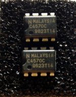
"They clearly don't look like indians to me 🙂 Make Malaysia great again!"BTW here are my μPC4570C samples (the NEC similar low noise chip to the 5532 we talked about for a bit), do they look legit to those of you who met them in older Japanese audio machines?
Here are two versions, one from a Kenwood amp(a83), the other from a Gemini dj mixer, phono section
Attachments


Better explanation.Thanks!I think C411's job might be to slow the turn-on ramp so the pass transistor doesn't die trying to charge that boatload, giving the opamp and control loop a chance to come up and stabilize
"They clearly don't look like indians to me 🙂 Make Malaysia great again!"
Here are two versions, one from a Kenwood amp(a83), the other from a Gemini dj mixer, phono section
Thanks for verifying.

Just for the sake of history...
Any DIY or rolling plans for those famed originals ?
Possible replacement for NE5332
Pardon me for exhuming this old discussion.
I recently bought the B-version of the TPA3255-amp from 3e Audio. Besides some worsening compared with the A-version - the print terminals has been replaced by cheaper tab connectors - the input op amp is pluggable now.
The design of the 3e amp follows mainly the TPA3255EVM from TI. The input op amp is a NE5332, which is already quite a reasonable audio op amp.
I wouldn't be here if I wasn't looking for some tweaking. Which op amp do you think I should give a try?
Thank you for your hints.
Robert
OPA1656 is the newest hot-shot on the block. Might give that a try.
OPA1656: High-Performance CMOS Audio Op Amp
OPA1656: High-Performance CMOS Audio Op Amp

- Home
- Source & Line
- Analog Line Level
- Drop in replacement for NE5532?