Pin 1 is often connected to audio ground inside the equipment. It's known as the pin 1 problem, this link should help: Pin 1 Revisited
Thank Andrew and Matt for the input. Very good reading material and fun as well. I think I'll do as follows : separate the pin 1 solder islands from the ground plane and put a wire between this and the xlr chassis point contact. I think that's more reliable than the plug's shell because not all xlr cables have their shell connected to the shield/pin 1. I wonder if the other builders or Carl as designer of the pcb would like to share their thoughts on this.
The best pin 1 solution is to wire pin 1 directly to the chassis with one of the plug mounting screws. Don't run anything from pin 1 inside the chassis!
Jan
Jan
Hi Jan, you mean via the plug's shell?The best pin 1 solution is to wire pin 1 directly to the chassis with one of the plug mounting screws. Don't run anything from pin 1 inside the chassis!
Jan
Hi Jan, you mean via the plug's shell?
I assume you use some screws to screw the connector to the (metal) chassis, no? A solder eyelet on one of those screws is a good pin 1 tie point. Like the picture Andrew showed a few pages back. Which is from Bruno's article.
See Linear Audio | your tech audio resource
Jan
There is a contact in the chassis that touches the chassis and the plug's shell. To get to pin 1 I'll have to be inside the chassis because the rest is plastic. I'll post a picture of the chassis tomorrow.I assume you use some screws to screw the connector to the (metal) chassis, no? A solder eyelet on one of those screws is a good pin 1 tie point. Like the picture Andrew showed a few pages back. Which is from Bruno's article.
See Linear Audio | your tech audio resource
Jan
There is a contact in the chassis that touches the chassis and the plug's shell. To get to pin 1 I'll have to be inside the chassis because the rest is plastic. I'll post a picture of the chassis tomorrow.
Yes the pin is on the inside, and that needs to be connected with a short wire to the chassis as close as possible.
Don't trust the shell contact.
Look at Andrew's picture and the one in my link.
Jan
BUILDERS NOTE: * XLR Pin1 Grounding *
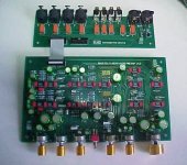
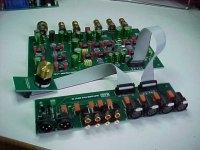
Note that the IO PCB that I delivered ties pin1 to the internal circuit ground. This is not an uncommon practice for consumer gear and works as expected 99% of the time. If your desire is to ground the XLR Pin1 to the chassis you must use a different XLR connector than the one specified in the BOM. Instead use an XLR whose pins extend straight out the back rather than down to the PCB. Doing this allows you to route pin 1 to the chassis using a short wire. You will also need to run short wires between pins 2 and 3 to the PCB.
Note that the IO PCB that I delivered ties pin1 to the internal circuit ground. This is not an uncommon practice for consumer gear and works as expected 99% of the time. If your desire is to ground the XLR Pin1 to the chassis you must use a different XLR connector than the one specified in the BOM. Instead use an XLR whose pins extend straight out the back rather than down to the PCB. Doing this allows you to route pin 1 to the chassis using a short wire. You will also need to run short wires between pins 2 and 3 to the PCB.
Last edited:
Thanks guys for the extensive information. Although I've read some of it in the past it's just now that I realise the practical implications. I'm not sure that I'll be having problems with the designed layout but historically I've often been part of the 0.01%. So I'll use Carl's suggestion and swap the sockets and do the wiring manually. Thanks again for all your help guys.
Happy Holidays!
Happy Holidays to everyone on this thread. I hope that you all have enjoyed building this project and enjoy listening thru it regularly.
Thanks again to Douglas Self for contributing the design to the DIY community and Jan Didden for publishing it.
And may we all experience a great new year!


Happy Holidays to everyone on this thread. I hope that you all have enjoyed building this project and enjoy listening thru it regularly.
Thanks again to Douglas Self for contributing the design to the DIY community and Jan Didden for publishing it.
And may we all experience a great new year!


one kit available ?
Hi Carl, Happy holiday too, i just heard of this project, and i see you made a new run one month ago ; is it still possible to get this kit ? thank you very much for this nice work !
Hi Carl, Happy holiday too, i just heard of this project, and i see you made a new run one month ago ; is it still possible to get this kit ? thank you very much for this nice work !
Hi Carl, Happy holiday too, i just heard of this project, and i see you made a new run one month ago ; is it still possible to get this kit ? thank you very much for this nice work !
Yup I have a few. I have sent you a private message.
Not sure what images are meant to be in post #930 😀 Carl as account holder of the images may see things look normal... others may not.
photo bucket
I see this 😉

photo bucket
I see this 😉
Attachments
Thanks again to Douglas Self for contributing the design to the DIY community and Jan Didden for publishing it.
You're most welcome. I am pleased that there appear to have been no significant technical issues in the making of many preamps.
The compliments of the season to you all.
I probably shouldn't say this, but only yesterday someone asked me if the Elektor 2012 preamp could be redesigned to make it quieter. Now that would be a challenge...
Quieter? Pots lower than 1k? Better/newer chips than LM4562?
Well, exactly. The 2012 preamp required some rather special design to make 1k pots usable, and going lower than that is going to double the number of opamps, if nothing else.
An active-passive volume control will improve noise performance at low volumes but requires a 4-gang pot. See Chapter 13 in my Small Signal book. (2nd edition only)
It is a problem that would require quite a bit of work, but I think it is do-able.
Whether it's a good use of time and resources is another matter...
There is already problem number 1 for me: 4-way potentiometers are very expensive or difficult to obtain. I have been playing for quite some time with an active Baxandal volume control. What worries me is the characteristic. At 25% pot position you have just ~ -12dB. More would be better (e.g. -25 ..- 30dB).
- Home
- Source & Line
- Analog Line Level
- Doug Self Preamp from Linear Audio #5

