The band shows the outer connection of the foil and can be used to shield the internal part of the cap from hum/noise pickup if you connect it suitably.
For example if the cap were across an audio input to ground you would connect the band to the ground end. If it were a feedback cap across an opamp output and input then you would connect the band to the opamp output to make use of the low impedance at that point.
Attachments
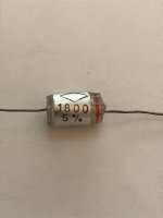
That's it. If you look at it end on you should see the lead at the banded end connecting to the outer wrap of the foil.
Many solid state circuits are low enough impedance that capacitor polarity isn't an issue - signal impedances are often sub-1k which isn't going to pick up much unless you run mains wires directly above the components. A stray capacitance of 1pF from 240V mains is equivalent to 75nA rms current injection, which at 1k is 75µV or -82.5dBV. The larger the cap the more stray capacitance there will be of course.
I'd worry about routing the wiring carefully first, and choosing shielded cables where appropriate. Shielding mains wiring is seldom done, but a great idea...
I'd worry about routing the wiring carefully first, and choosing shielded cables where appropriate. Shielding mains wiring is seldom done, but a great idea...
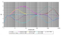
Would it be possible to see response curves of 3dB or 4dB boost for the bass turnover points and -1 or -2dB for the treble points? Trying to get an idea of the behavior at modest tone levels. Thank you!
"Would it be possible to see response curves of 3dB or 4dB boost for the bass turnover points and -1 or -2dB for the treble points? "
I don't remember where this graphic came from but I do remember that it closely matched what I was seeing when I modeled the tone controls using my aging CircuitMaker software. I find the tone controls to be very usable and pleasant to listen to. I invite others to offer up with their opinions.
I don't remember where this graphic came from but I do remember that it closely matched what I was seeing when I modeled the tone controls using my aging CircuitMaker software. I find the tone controls to be very usable and pleasant to listen to. I invite others to offer up with their opinions.
Attachments
Thank you Carl_Huff,
I admire the adjustable turnover frequencies. I was hoping the diy version of the fabulous Cello Palette tone preamp would take off, but the project never became a PCB.
Reading through this discussion, you’ve done a great job putting together the boards for a capable preamp.
I admire the adjustable turnover frequencies. I was hoping the diy version of the fabulous Cello Palette tone preamp would take off, but the project never became a PCB.
Reading through this discussion, you’ve done a great job putting together the boards for a capable preamp.
Hi,
I would like to know if someone had printed the pots setup drawing on acrylic in order to be screwed on the front plate or made a screen to print them in a wood front plate ?
For me it's the difficult part in preamp projects. I'm ok on soldering and smd but casing is the big problem and I don't want to spent much on the casing. I go often with wood.
Many thanks for your link if existing for this pre 🙂
The fpd file doesn't fit the panel I made but what was made only fgor the EQ pots panel here could be quite cool : Doug Self Preamp from Linear Audio #5
Any supplier for such little panels in Europe ?
Any supplier for such little panels in Europe ?
Cello Palette preamp
" I was hoping the diy version of the fabulous Cello Palette tone preamp would take off, but the project never became a PCB."
That sure would be a fun and worthwhile project. I will look into this and see what I can do.
" I was hoping the diy version of the fabulous Cello Palette tone preamp would take off, but the project never became a PCB."
That sure would be a fun and worthwhile project. I will look into this and see what I can do.

Thank you very much. There is a schematic for the discrete version floating around in the Cello Audio Palette thread and elsewhere on the web. The boards are a bit of a nightmare in that thing. A well laid out opamp based version may be easier and just as capable.kouiky said:I was hoping the diy version of the fabulous Cello Palette tone preamp would take off, but the project never became a PCB.
That sure would be a fun and worthwhile project. I will look into this and see what I can do.
Will any more of the Doug Self Preamp from Linear Audio #5 boards be available in the future?
"Will any more of the Doug Self Preamp from Linear Audio #5 boards be available in the future?"
I have them now if you are interested. Message me for details.
I have them now if you are interested. Message me for details.
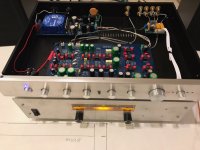
Finished Pre-Amp
Took a while...Lots of resistors and caps!
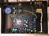
I decided not to incorporate the balanced inputs and to make the input selector I used work, I eliminated R53 L/R and put a ground on Pin 3 of the output also did the same for R1 L/R but put a ground on pin 2 of the input. This way the 3 pin plugs on the input selector worked. Also I powered the Power LED from the mainboard with a dropping resistor and installed a 2 pin connector. I ended up building the chassis to signal ground idea from Elliott Sound under his power supply section.
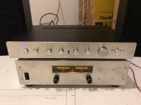
I purchased the Dun Mei Audio AV39 chassis. To countersink the holes I used a flat wood boring bit with a drill press so the knobs set in the face plate. REAL FUN!!
I set the power supply voltage to +/- 17.6 vdc per the reading in this thread. If this is wrong, please let me know.
The Sound is a very close match to my Yamaha C-50. Subtle difference of course is with the balance. The Yamaha does not have this type of balance.
I'll eventually setup a pair of Cerwin Vega D8-E's and do some comparison tests. For now I'm just using a pair of Fisher studio monitors.
It sounds very good through them.
Took a while...Lots of resistors and caps!
I decided not to incorporate the balanced inputs and to make the input selector I used work, I eliminated R53 L/R and put a ground on Pin 3 of the output also did the same for R1 L/R but put a ground on pin 2 of the input. This way the 3 pin plugs on the input selector worked. Also I powered the Power LED from the mainboard with a dropping resistor and installed a 2 pin connector. I ended up building the chassis to signal ground idea from Elliott Sound under his power supply section.
I purchased the Dun Mei Audio AV39 chassis. To countersink the holes I used a flat wood boring bit with a drill press so the knobs set in the face plate. REAL FUN!!
I set the power supply voltage to +/- 17.6 vdc per the reading in this thread. If this is wrong, please let me know.
The Sound is a very close match to my Yamaha C-50. Subtle difference of course is with the balance. The Yamaha does not have this type of balance.
I'll eventually setup a pair of Cerwin Vega D8-E's and do some comparison tests. For now I'm just using a pair of Fisher studio monitors.
It sounds very good through them.
Attachments


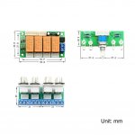

an acrylic screen with the marking for at least what is on the board : EQ and Volume pot and balance (not source selection, this one being be positioned at right or left where the diyer wants best.
That's beautifull 90Scaraudio,
An acrylic screen with 4 holes a printed screen for the pots markings would permit to see the metal casing as well as the wood panels for those having one and perhaps would be less expensive than the metal printed one (around 100 USD and more just the front panel).
Any ideas where to source that, folk ?
Thanks all. I should have mentioned the Amp... I put together a pair of LJM's L12-2 amps. More pics in that thread...
L12-2 CFP Output amp 120W*2 8R
L12-2 CFP Output amp 120W*2 8R
this little amp cheap kit is said to sound very good ! how do you find it ?
For $33 plus $7 for shipping
 It actually sounds fantastic and it stays cool. Lot of info on these... I also built the MX50SE and it also sounds fantastic.
Took a while...Lots of resistors and caps!
I decided not to incorporate the balanced inputs and to make the input selector I used work, I eliminated R53 L/R and put a ground on Pin 3 of the output also did the same for R1 L/R but put a ground on pin 2 of the input. This way the 3 pin plugs on the input selector worked. Also I powered the Power LED from the mainboard with a dropping resistor and installed a 2 pin connector. I ended up building the chassis to signal ground idea from Elliott Sound under his power supply section.
I purchased the Dun Mei Audio AV39 chassis. To countersink the holes I used a flat wood boring bit with a drill press so the knobs set in the face plate. REAL FUN!!
I set the power supply voltage to +/- 17.6 vdc per the reading in this thread. If this is wrong, please let me know.
The Sound is a very close match to my Yamaha C-50. Subtle difference of course is with the balance. The Yamaha does not have this type of balance.
I'll eventually setup a pair of Cerwin Vega D8-E's and do some comparison tests. For now I'm just using a pair of Fisher studio monitors.
It sounds very good through them.
I was told that the power supply should be set to +/-15vdc for the LM4562 Op Amps. Adjustment made, sounds the same, components are a little cooler.
Perfect🙂
- Home
- Source & Line
- Analog Line Level
- Doug Self Preamp from Linear Audio #5