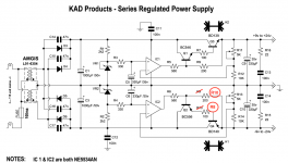
Doug this is for the opamps of Carl's regulated power supply for your preamp Sorry for the confusion..
The opamps voltage is the voltage after the rectifiers see attached..
For the Series Regulated PS there seems to be some minor discrepancies between the schematic and the PCB silkscreen related to R7-R10. I've put an inquiry into Carl. Hicoco and others, how did you populate yours?
BK
Yes, i noticed that there are a mistake on the negative rail for R10 and R8 when i populated my board with the schematique.. otherwise R7 and R9 in the positive rail are good.For the Series Regulated PS there seems to be some minor discrepancies between the schematic and the PCB silkscreen related to R7-R10. I've put an inquiry into Carl. Hicoco and others, how did you populate yours?
BK
Attachments
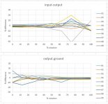
Just for giggles I measured the channel imbalance of 9 samples of the Alpha 5k linear pots from Tayda. A couple outliers, so I'll pick the best for the 6 positions and the flattest for the volume control.
BK
Every mechanical volume pot has 20% tolerance.
Just for giggles I measured the channel imbalance of 9 samples of the Alpha 5k linear pots from Tayda. A couple outliers, so I'll pick the best for the 6 positions and the flattest for the volume control.
BK
What's going on at 75% ?? Do these pots have a tap, or did you use a resistor from wiper to gnd?
Jan
Not if you're rich enough:Every mechanical volume pot has 20% tolerance.
5611R10KL.152G BI Technologies / TT Electronics | Mouser United Kingdom
Last edited:
What's going on at 75% ?? Do these pots have a tap, or did you use a resistor from wiper to gnd?
Jan
Measured directly at the terminals. I've experience variation in similar products, so I'm in the habit of getting extras and cherry picking the best of the bunch. After all, these are only $0.80/ea delivered.
BK
I seem to remember from the article that the tolerance of the pots is very forgiving. Wouldn’t that mean that this exercise is unnecessary?
I seem to remember from the article that the tolerance of the pots is very forgiving. Wouldn’t that mean that this exercise is unnecessary?
Of course probably unnecessary! Just cost a bit of my time. And I get the satisfaction of knowing that I did my best.
BK
Old fashion regulated PWR Supply problem......
Look like i have a serious problem with this series Regulated PWR Supply.
I changed the Transfo for an +-15V 25VA
With no load i am able to adjust the output at +-17Vdc or more.
With 200mA load at the positive rail and 180 mA at the negative rail i have +-15 Vdc and not able anymore to adjust the voltage at a value higher than 15 Vdc when i turn the adjustable Pot.
I have at the primary 241Vac and after transfo 2x18,5Vac, after rectifiers +-25Vdc with no load and +-21,8 Vdc with the load.
Just a reminder i am able to adjust at +-17Vdc with a 2X18vac transfo but the BD139 is abnormally hot after 10 mns (61℃)(142ºF)
Carl your thought please.....
i have +-25Vcc after rectifiers18.5V is very low for a 17V supply. 20-22VAC would be fine.
BK, do you have an answer from Carl for your inquiry?? and did you test your power supply??For the Series Regulated PS there seems to be some minor discrepancies between the schematic and the PCB silkscreen related to R7-R10. I've put an inquiry into Carl. Hicoco and others, how did you populate yours?
BK
FR
BK, do you have an answer from Carl for your inquiry?? and did you test your power supply??
FR
Yes, Carl agreed the schematic had an error as indicated. The image you posted is correct and that is how I built mine. I tested without load and everything seemed fine. Very smooth and wide adjustment via the trimmers, no excessive heat after 30min set to +/17V. I ordered some 100ohm power resistors to load test while I build the enclosure. I used MUR820 diodes and matched BC550/BC560 for hfe only because I have a large stash (note the BOM had these reversed!).
BK
yes, that is fine also for me too with no load and +-17V after 2 hours, no heat. i used also BC550/BC560. I have excessive heat with load after 10 minutes.Yes, Carl agreed the schematic had an error as indicated. The image you posted is correct and that is how I built mine. I tested without load and everything seemed fine. Very smooth and wide adjustment via the trimmers, no excessive heat after 30min set to +/17V. I ordered some 100ohm power resistors to load test while I build the enclosure. I used MUR820 diodes and matched BC550/BC560 for hfe only because I have a large stash (note the BOM had these reversed!).
BK
yes, that is fine also for me too with no load and +-17V after 2 hours, no heat. i used also BC550/BC560. I have excessive heat with load after 10 minutes.
So that I am clear about this ...
The power supply heats up you connect it to the preamp PCB? Or does it heat up just idling without being connected?
There is no heat with no preamp PCB or no load.So that I am clear about this ...
The power supply heats up you connect it to the preamp PCB? Or does it heat up just idling without being connected?
That heat up after i connected the preamp PCB or any load ( i tried also with power resistors to load test)
There is no heat with no preamp PCB or no load.
That heat up after i connected the preamp PCB or any load ( i tried also with power resistors to load test)
What value load resistors are you using?
Do you get clean signals thru both preamp channels when connected to it?
There might be a problem on the preamp board. You could have a bad or backward op amp or solder bridge.
- Home
- Source & Line
- Analog Line Level
- Doug Self Preamp from Linear Audio #5