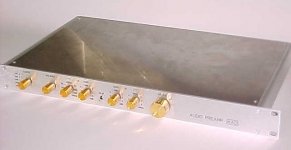
The green pots are OMEG eco pots. Only 4k7 not 5k, but seem to work well.
The extra pcb is just a primitive power supply to drive the power switch and selector LEDs.
Great!
Have you measured them for channel imbalance? There are several builders reporting this problem, especially at low volume setting.
Great!
Have you measured them for channel imbalance? There are several builders reporting this problem, especially at low volume setting.
Is this using the Alps clone, which I have just bought 10 off for £7 which is too cheap for my piece of mind.?
(I didn't spot them on Rapidonline's website but fortunately I've not yet started the build)
Omeg 2GECO22KLIN 22K ECO 16mm Linear Dual Control | Rapid Online
Is this using the Alps clone, which I have just bought 10 off for £7 which is too cheap for my piece of mind.?
(I didn't spot them on Rapidonline's website but fortunately I've not yet started the build)
Omeg 2GECO22KLIN 22K ECO 16mm Linear Dual Control | Rapid Online
Not sure, but there may a channel imbalance due to pot manufacturing.
I don't have that problem in my build and I have used the Alpha pots.
I have ordered much more than I needed and here's how I have tested them.
Wired each of them as a Wheatstone bridge and measured the voltage difference as slowly turned the pot shaft.
Then selected the ones showed the lowest voltage differences.
Might try that as the omeg one is out of stock everywhere. I almost ordered 22k ones but spotted my mistake in time.
cpc-farnell are expecting 100 on 24th September
Last edited:
Realistically you are going to see balance issues at very low volume settings due to manufacturing tolerances.
Need to gain stage the signal chain such that the pot' is normally operating well away from 'bottom'.
Need to gain stage the signal chain such that the pot' is normally operating well away from 'bottom'.
Realistically you are going to see balance issues at very low volume settings due to manufacturing tolerances.
Need to gain stage the signal chain such that the pot' is normally operating well away from 'bottom'.
Totally agree
I did not check before building, but did check one I had lying around.
There was a differential ranging from 0.48% to 1.46%. Interestingly the worst was at mid rotation. I certainly can't hear a difference.
There was a differential ranging from 0.48% to 1.46%. Interestingly the worst was at mid rotation. I certainly can't hear a difference.
I did not check before building, but did check one I had lying around.
There was a differential ranging from 0.48% to 1.46%. Interestingly the worst was at mid rotation. I certainly can't hear a difference.
Hi. What were you measuring ? eg. the difference in absolute resistance value between tracks at the wiper position ? or the ratio of the resistance at the wiper position relative to the track resistance ? or the voltage at the wiper posion (with the same refence applied to bothe tracks ) ? etc
Hey Carl Huff beautiful build! I just got my boards and am looking for casing. Is that a front panel design? Can you give me details on your case? Would you be willing to share if it is a front panel design?
Hi. I'm sure that there is a correct way to measure the imbalance. However what I did was check the resistance of both tracks at full rotation and found a 120R difference.
I the did readings at various positions of rotation. I then expressed these readings as percentage of that tracks total resistance. The difference between the tracks for each position is what I quoted.
Ps could you let me know the correct method
I the did readings at various positions of rotation. I then expressed these readings as percentage of that tracks total resistance. The difference between the tracks for each position is what I quoted.
Ps could you let me know the correct method
Hey Carl Huff beautiful build! I just got my boards and am looking for casing. Is that a front panel design? Can you give me details on your case? Would you be willing to share if it is a front panel design?
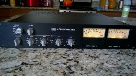
If you are looking at the PICs in my recent post, that is Ashley's build. And you are right, he did an excellent job. Attached below are a couple of examples of ones that I have built.
The FPD files for their front panels are here: Dropbox - FRONT_PANEL_EXPRESS.zip
Attachments
So do you know anything about Ashleys build? Possibly a front panel design that we could share?
So do you know anything about Ashleys build? Possibly a front panel design that we could share?
I invite Ashley to verify, but I think that he took the FPD file that I provide, modified it a bit for his purposes using the 'Front Panel Designer' editor that the service provides and (as my British friends would say ...) 'Bob's your uncle!'
Hi. I'm sure that there is a correct way to measure the imbalance. However what I did was check the resistance of both tracks at full rotation and found a 120R difference.
I the did readings at various positions of rotation. I then expressed these readings as percentage of that tracks total resistance. The difference between the tracks for each position is what I quoted.
Ps could you let me know the correct method
Well I don't think there's a 'correct' way - was simply interested in what exactly being measured and how.
Your method sounds good to me.
Personally I'd probably rig up a reference voltage to each track and read voltages at the wiper positions. Saves having to reference each reading back to the absolute track resistance - you just have ,say, 10V across the track . Read the voltages and it's easy sums 🙂
Also reduces the influence of test probe/clip contact resistance and test lead resistance.
But it would depend on what instrumentation I had available.
eg if I had a good dedicated resistance meter but only a mediocre DMM I might go with your setup. And it also saves needing an accurate reference voltage.
Carl you are absolutely right, I did use your design.
I checked with some of our local island businesses to see who would be prepared to take on laser engraving. (its not a big island ) One company was enthusiastic and immediately took your design and my rough sketches of the changes and set it all up. A bit lazy on my part, but it turns out that he is planning to join us with a guitar amp build.
RMaudio thanks for your advice, something I will try.
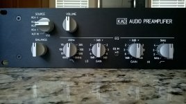
Here is a PIC of what I propose to be the front panel layout. The 'gold colored' circles are 15mm diameter control knobs.
Note the centrally located toggle switch that when operated to the down position bypasses the tone controls.

Carl,
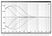
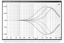
I think the frequency control range does not match with DS curves in the LA5 article. Correct me if wrong.
Best Regards
Farooq
Attachments
Carl,
I think the frequency control range does not match with DS curves in the LA5 article. Correct me if wrong.
Best Regards
Farooq
Farooq,
The panel markings are subject to debate but the circuit performance should be identical to what is plotted, as it is identical to what Doug published in his article.
Farooq,
The panel markings are subject to debate but the circuit performance should be identical to what is plotted, as it is identical to what Doug published in his article.
yes that is correct. In my case frequency control is working correctly as per article and I prefer Max. for LF and Min. for HF.
back-panel
nice front panel ! is there also a design (FPD files) for the back-panel you can share on this forum ?
nice front panel ! is there also a design (FPD files) for the back-panel you can share on this forum ?
If you are looking at the PICs in my recent post, that is Ashley's build. And you are right, he did an excellent job. Attached below are a couple of examples of ones that I have built.
The FPD files for their front panels are here: Dropbox - FRONT_PANEL_EXPRESS.zip
nice front panel ! is there also a design (FPD files) for the back-panel you can share on this forum ?
Well ...
Unfortunately I never got around to making any but expect others have. I invite them to post those to this thread.
- Home
- Source & Line
- Analog Line Level
- Doug Self Preamp from Linear Audio #5