Thanks for sharing.Apologies to Richard to thread OT but I'll just add this for bench2005.
I don't think the Pi clock is a game changer if this is just a start out piece of gear or maybe not for your main system. My first dabble with Rpi and a Hifibery DAC wasn't great. I added a seperate PSU and an isolator and things got a whole lot better. Even without the isolator the seperate PSU helped a lot. And this won't effect you as you won't be using Rpi gpio for power to the Dorati.

Hi all,
After a long delay (too many things to do too little time), I finally got my soldering iron out and finish the Dorati. I follow the three steps and all is well until step 2 & 3. The following are the readings from all the different TPs:
Step 1
TP1 4.81v
TP2 2.476v
TP3 1.655v
TP8 4.98v
Step 2
TP6 5.84v
TP9 7.04v
TP10 5.63v
TP12 6.82v
Step 3
TP4 4.45v
TP7 4.23v
Step 1&2 were done without any i2s signal and the power supply measured at 13.42v, current draw is 136mA and Step 3 was done with when I play something through i2s and it does play. As can be seen, TP10/12 is bit low and both TP4/7 were low as well.
I checked all the solder joints and as far as I can tell they are ok.
As I say, it does play, but I am not sure if it is functioning as it suppose to.
Can anyone give me some pointers on this?
Many thanks,
Bench
It looks to me like you did have a problem with TP10 - hence with Q27 and Q15 and closely related components. But now you've fitted the inductors whatever issue that was is masked. But its possible that issue is the reason TP7 is now so low. Would you be able to take a picture of your board to include those transistors Q27, Q15 and the I/V resistors R49 & R36?
Hi,It looks to me like you did have a problem with TP10 - hence with Q27 and Q15 and closely related components. But now you've fitted the inductors whatever issue that was is masked. But its possible that issue is the reason TP7 is now so low. Would you be able to take a picture of your board to include those transistors Q27, Q15 and the I/V resistors R49 & R36?
Pls. see attached photos.
Thanks - there looks to be something a bit strange about the soldering on Q27 collector (the bottom most pin of Q27). Maybe give it another visit with the iron?
Unrelated to your TP measurements, C19 right contact might not be making good connection to the pad. Looks like the pad didn't get wetted?
Unrelated to your TP measurements, C19 right contact might not be making good connection to the pad. Looks like the pad didn't get wetted?
Will give those joints a quick once over and see if that fixes it. Will let u know how it goes. Many thx for looking into it.Thanks - there looks to be something a bit strange about the soldering on Q27 collector (the bottom most pin of Q27). Maybe give it another visit with the iron?
Unrelated to your TP measurements, C19 right contact might not be making good connection to the pad. Looks like the pad didn't get wetted?
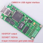
I want to ask you if anyone has compared the sound of Dorati and PhiDAC hex 2020, 7th order filter. I have it working for a long time. It worked without problems. The photo shows a usb digital interface. At that time I bought a used Sony WM1Z. I did a mod replacing capacitors, wires and removed the output relay. Changed the software. I use it with headphones and also with Hugh R. Dean's Saksa85 power amplifier. PhiDAC is in a drawer. I plan to make a non-portable dac version for the Saksa85. I will either use PhiDAC hex or order Dorati. Thanks everyone for your help.
Attachments
Last edited:
Hi Peter - while I haven't listened to Phi hex side by side with Dorati, I might be able to give you some indication of the difference. The 'hex' was designed before I realized how important low noise was in an I/V stage so it doesn't have the acoustic 'bloom' that my later DAC designs have. However the 7th order filter (compared to Dorati's 3rd order) means that on close-miked piano for example the instrumental timbre is more true to life.
Incidentally, 'hex' could be upgraded to give lower noise through some component changes in the output stages. If you're interested in how to do that, shout. For a start the AD829 can be swapped to LT1028. This isn't a direct substitution though, it needs a small change to the circuitry. AD744 can be swapped for a lower noise JFET such as OPA1641 along with some component value changes to take advantage of the 1641's lower noise.
Thank you for your response. I made a class A headphone amplifier. It was designed by Hugh R. Dean along with Xrk971. Altoids pocket Class A. Is it possible to take the signal from the TDA1387 output and amplify it with this amplifier? To try it out.Incidentally, 'hex' could be upgraded to give lower noise through some component changes in the output stages. If you're interested in how to do that, shout. For a start the AD829 can be swapped to LT1028. This isn't a direct substitution though, it needs a small change to the circuitry. AD744 can be swapped for a lower noise JFET such as OPA1641 along with some component value changes to take advantage of the 1641's lower noise.
I'd not recommend taking a signal direct from the TDA1387 as that'll be unfiltered. You could use a resistor to terminate the LC filter and feed the voltage across that resistor into your xrk971 amp. That would likely work well though I don't know what the input sensitivity of the amp is. so I'm unclear if you'd have enough gain.
abraxalito, can you send me a pm? I am interested in purchasing some kits but cant send a pm still.
Last edited by a moderator:
From this place? And what resistor value should I use?I'd not recommend taking a signal direct from the TDA1387 as that'll be unfiltered. You could use a resistor to terminate the LC filter and feed the voltage across that resistor into your xrk971 amp. That would likely work well though I don't know what the input sensitivity of the amp is. so I'm unclear if you'd have enough gain.
Attachments
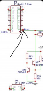
47ohm is the terminating resistor, and it needs to terminate to a DC voltage between 5.5 and 6V to remain within the compliance range of the DAC chips. Yes, you got the right place.
Orders now are open on Dorati NOS DAC kits - PM me and be sure to include your payment method and location so I can quote you inclusive of fees and shipping.
Greetings. I want to order a Dorati NOS DAC kit, but I'm a new user and so I can't write private messages yet. Please @abraxalito write to me and we will proceed to order details
Hello,
I've slowly completed my Dorati but I 've the same problem of BENCH2005,
I followd the three steps and all was well until step 3. The following are the readings from all the different TPs on Step 3:
TP1 4.82V
TP2 2.49V
TP3 1.66V
TP8 4.98V
TP6 568V
TP9 6,90V
TP10 5,46V
TP12 6.68V
TP4 4.35V
TP7 4.23V
PSU is 12,10V 140 mA
I checked all welds and component values. I also replaced Q27 and Q15 without any appreciable results.
The Dac seems to work perfectly.
What can I check now.
Best regards.
Guglielmo
Hi Guglielmo - assuming that TP6 lost a decimal, was supposed to be 5.68V then those voltages all look fine. There is quite a variation in TPs because the DAC chips' output current has a wide variation (around 30%).
You say it plays? Then you're good!
You say it plays? Then you're good!
Hello Richard,
well now I will listen to it at my leisure. Now I would like to use these dacs (a Dorati and a Celibidache) connected in I2S to a nanodigi minidsp, in your opinion which are the frequencies preferred by each of your dacs? Let me explain: for example, which dac would you use to reproduce low frequencies and which one to reproduce high frequencies or medium frequencies?
Thanks and have a good audio weekend.
Guglielmo
- Home
- Vendor's Bazaar
- Dorati NOS DAC kits