Here's the picture of the speaker
http://img33.imageshack.us/img33/9614/speakerq.png
It's brand is called 'Thorn'.
All I know is that it's a 8 Ohm speaker. But that's about it.
Well, I think it has only 5-10 Watts of rated power. 🙄
Simply do the following: take off the old speaker itself from this wood enclosure, and build the suitable auto speaker into this enclosure. 😀 The modern auto speakers are usually rated for much higher power at the same size, than old paper speakers... 😉
Ok I have a spare if I Mess it Up 😀
So I'll give it a go.
I'm apparently required to make it a bit more user friendly. So I got a bit of editing to do now on my board.
Nothing more to add to today (Not at the top of my head at least 🙄 ).
Mostly just been mechanical work today. Designing the frame for the board and all.
Mostly just been mechanical work today. Designing the frame for the board and all.
Ok question has popped up now. I am building a box basically to put the veroboard into. So I'll be using Wall Mounting Plugs for the music input, power supply and speaker output. So it's more user friendly.
And on the inside I will solder wires from the plugs into the veroboard. This should be fine right? Or will I see Aerial effects or other nasties cause of this?
I'll Be moving the Pot as well more or less. So it's connections will have 3 wires connected from POT to copper track, instead of directly being soldered onto the tracks.
Hopefully that 100pF cap does the job once I've soldered bits and pieces around and there's more wires.
And on the inside I will solder wires from the plugs into the veroboard. This should be fine right? Or will I see Aerial effects or other nasties cause of this?
I'll Be moving the Pot as well more or less. So it's connections will have 3 wires connected from POT to copper track, instead of directly being soldered onto the tracks.
The sound input wires or wires from the volume pot can act as an antenna and produce various 'effects'. So, place the 100pF cap between the sound input and the ground, directly on the TL494 pins maybe
Hopefully that 100pF cap does the job once I've soldered bits and pieces around and there's more wires.
Last edited:
Ok question has popped up now. I am building a box basically to put the veroboard into. So I'll be using Wall Mounting Plugs for the music input, power supply and speaker output. So it's more user friendly.
And on the inside I will solder wires from the plugs into the veroboard. This should be fine right? Or will I see Aerial effects or other nasties cause of this?
I'll Be moving the Pot as well more or less. So it's connections will have 3 wires connected from POT to copper track, instead of directly being soldered onto the tracks.
Yes, this should be ok. 😉 And this is why it was needed to have the capacitors around pins 15 and 16 of TL494: they should protect the amp's input from various parasitics (even more from amp's own parasitics 😀)...
Also, when doing the wired connections to the veroboard, try to use twisted wire pairs everywhere: from input connector, to volume pot, speaker connectors, power plug connector, etc. Simply twist two wires together from each connector always, like it is done in Ethernet CAT5 cable, for example. This should protect from radiating and receiving EMI effectively, I think... 🙄
This should protect from radiating and receiving EMI effectively, I think...
If signal is unbalanced, then twisting doesn't change capacitive coupling, it is effective against inductive coupling only. Shielded (coaxial) wire is effective for both.
If signal is unbalanced, then twisting doesn't change capacitive coupling, it is effective against inductive coupling only. Shielded (coaxial) wire is effective for both.
Alright then I will buy shielded Wire.
Oh by the way. The crackling noise I was hearing that made it sound like it was being High Pass Filtered was cause of the PC. I was using the front Headphone outlet as my input. Switching to MP3 gives me a clean music.
Last edited:
So I'll just hear more distortion if I don't use shielded cable.
I'm having the worst luck trying to find a 3.5mm Mono to Mono cable connection. So I might be making one myself at this rate with the regular cables I used for connection on my board.
I'm having the worst luck trying to find a 3.5mm Mono to Mono cable connection. So I might be making one myself at this rate with the regular cables I used for connection on my board.
I'm not going to take the connectors out (Or should I?).
I'll just move the pot and have wires for that. But otherwise I'll wall mount the input and output connection for the music and speaker and carry wires over to the connector on the board (Rather then physically solder it on the board). I'll do the same with the Power Supply as well.
I'll just move the pot and have wires for that. But otherwise I'll wall mount the input and output connection for the music and speaker and carry wires over to the connector on the board (Rather then physically solder it on the board). I'll do the same with the Power Supply as well.
All the framework for it is all done. The soldering is all I have to now.
Also I was able to get my hand on some shielded coaxial wires. Which I'll use for the pot, input music and output speaker. I'll just use regular wires for the power supply.
Also I was able to get my hand on some shielded coaxial wires. Which I'll use for the pot, input music and output speaker. I'll just use regular wires for the power supply.
Last edited:
I'll just use regular wires for the power supply.
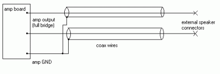
It is better to use twisted regular wires for output too, especially for full bridge output... In full bridge each output wire will conduct in antiphase, and if they are twisted (or phisically paralleled), then this will eliminate all parasitics.
Sure, it is possible to use coax wires too, but then I would like to connect them as it shown in then picture. 🙂
Attachments
Last edited:
It is better to use twisted regular wires for output too, especially for full bridge output... In full bridge each output wire will conduct in antiphase, and if they are twisted (or phisically paralleled), then this will eliminate all parasitics.
Alright I will use it in twisted pair fashion then.
Looks neat to me. I have the Power Supply connection at the back. The input music, volume knob and output speaker connection at the front.
It is better to use twisted regular wires for output too, especially for full bridge output... In full bridge each output wire will conduct in antiphase, and if they are twisted (or phisically paralleled), then this will eliminate all parasitics.
Sure, it is possible to use coax wires too, but then I would like to connect them as it shown in then picture. 🙂
Why two cables for output? The shielded cable I have has two threads already inside it. One if for output and the other is ground.
In my case wouldn't it just be the single cable with the extra insulated wire being the output and the other one being ground.
Although your the third person today who's told me to use regular wires at both the power supply and the output as well.
So I'll go with regular wires but in twisted pair fashion and just use coax for the input and pot.
Why two cables for output? The shielded cable I have has two threads already inside it. One if for output and the other is ground.
In my case wouldn't it just be the single cable with the extra insulated wire being the output and the other one being ground.
In this project you are using the full bridge configuration. So there is NO any 'ground' output wire. Both wires have an output signal with residual, etc. So you cannot simply say, that for example the wire A is a 'ground' wire and connect it to the shield of coax. Shield must be always connected to the GND, to get any effect from the coax cable. So, because of it there was needed to use two coax cables. 🙂
Although your the third person today who's told me to use regular wires at both the power supply and the output as well.
So I'll go with regular wires but in twisted pair fashion and just use coax for the input and pot.

In this project you are using the full bridge configuration. So there is NO any 'ground' output wire. Both wires have an output signal with residual, etc. So you cannot simply say, that for example the wire A is a 'ground' wire and connect it to the shield of coax. Shield must be always connected to the GND, to get any effect from the coax cable. So, because of it there was needed to use two coax cables. 🙂
Thanks for clarifying that further. 😀
yeah two threads. Once you remove the outer insulation, there's copper wire and another wire surrounded by another insulation.
The copper wire I was told was what goes to ground and the other wire surrounded by the second insulation is the input (Once you remove that insulation as well) .
The copper wire I was told was what goes to ground and the other wire surrounded by the second insulation is the input (Once you remove that insulation as well) .
Alright the amplifier itself is completed now. Now I have to analyze distortion and such. So I'll be making that circuit tomorrow.
But the framework looks good. Hope the teacher likes it. 🙂
Just to re-cap from yesterday, I used twisted pair fashion for both power supply and output to speaker. While I used Coaxial cable for pot and music input.
Mucking around with the wires inside the compartment wasn't easy. I'll tell ya that.
I do have one query about the volume knob. I get this enormous "HISSSS" noise in the background every time I touch it, which increases as you turn the volume up. I was told it was because I am using a metallic knob and I should switch to plastic. So I did switch to plastic, but the HISSS is still there. I'm told It's because I haven't earthed my Pot properly (it's shaft or something).
Any solutions to this problem?
I'm told It's because I haven't earthed my Pot properly (it's shaft or something).
Any solutions to this problem?
You know the solution already: just ground it properly 😉
I would suggest to connect the metal case of the pot with GND wire of your input coax wires... 🙄
You know the solution already: just ground it properly 😉
I would suggest to connect the metal case of the pot with GND wire of your input coax wires... 🙄
So a regular wire from the back panel to ground is enough?
Edit: Ok how about this. I solder a normal regular wire from the ground pin of the pot to the back metallic panel or the shaft?
- Status
- Not open for further replies.
- Home
- Amplifiers
- Class D
- Doing a class D Amp project using TL494