Hallo all.
I'm just curios of the current dumping design, I have build a Slewmaster, lateral Hitachi, P3A, Quasi type and a couple more. All great sounding amps.I just want to know if this amp is so much different in sound for the better. Reading about the Quad 405 that is being praised.Why are people not using current dumping designs if it is so great. 😕 I want to build something to keep me busy, I have thought about a Leach low Tim, but just wondering ?😀
Regards and have a great weekend !
Jan
In an active System I use a 405 clone for the tweeters and a DOGC for the lowend. I can highly recommend the DOGC. The 405 needs Heavy modifications to come close...
Just try DOGC ��
Regards, Michael
Just try DOGC ��
Regards, Michael
DOGC Tx Requirements
Hello,
I am interested in building a DOGC Amp by Dr. Jagodic.
Since I already have two torioidal transformes from another project (each 200VA and 2x24VAC) my question is if this would be sufficient for the
DOGC-MK3?
I understand from previous posts that recommendation for the DOGC-H would be min. 35VDC, does this apply for DOGC-MK3 as well?
Many thanks in advance!
Regards,
Werner
hi, i hope there is still someone listening here. I made the DOGC-H pcbs. as per the originals of the Bora site, and I have a 2x37v toroidal that should bring the DC to 52v and not 48v. Can I use it here? Will it work? thank you .
Hi,
52V should be fine. Make sure you have big enough heatsinks. DOGC-H dissipates little bit of heat.
52V should be fine. Make sure you have big enough heatsinks. DOGC-H dissipates little bit of heat.
Kacernator,
Have you actually solved your overshoot problem in post #33,34 ?
Fir example increasing the value of the 100p capacitor ?
Or put a 1.5n FKP2 across the 960R 1W ?
Do you have a spice model to try out first in simulation ?
Patrick
Have you actually solved your overshoot problem in post #33,34 ?
Fir example increasing the value of the 100p capacitor ?
Or put a 1.5n FKP2 across the 960R 1W ?
Do you have a spice model to try out first in simulation ?
Patrick
Hi,
52V should be fine. Make sure you have big enough heatsinks. DOGC-H dissipates little bit of heat.
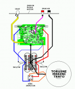
does the voltage increase from 48 to 52v x power the lf411 at 15v starting from the amplifier psu with resistor 3k9 2w , as per the diagram, does it not involve any problems? and ok also x frd110? thank you
Attachments
Something isn't complete here or something isn't clear.
You need 15v zener diodes after 3K3 resistors.
Positive side cathode to 3K3 anode to gnd.
Negative side anode to 3K3 cathode to gnd.
Are those zener diodes on the amplifier pcb?
You need 15v zener diodes after 3K3 resistors.
Positive side cathode to 3K3 anode to gnd.
Negative side anode to 3K3 cathode to gnd.
Are those zener diodes on the amplifier pcb?
Something isn't complete here or something isn't clear.
You need 15v zener diodes after 3K3 resistors.
Positive side cathode to 3K3 anode to gnd.
Negative side anode to 3K3 cathode to gnd.
Are those zener diodes on the amplifier pcb?
I think they are on the pcb
I used a separate PS with simple 317/337 regulator board I got cheap from ebay. IMO a better solution then resistors + zeners.
Yes, the zeners and some caps are on the Pcb but not in the schematic.
Yes, the zeners and some caps are on the Pcb but not in the schematic.
I do have a modified Quad 405 and some Cheap class D for comparison.
DOGC is playing in a different League. I am Glad I Build it ��
DOGC is playing in a different League. I am Glad I Build it ��
What rail voltage are you using ?
317/337 is limited to 1A max, not ?
(That would be 4W at most into 8 Ohm.)
And you do not have the square wave overshoot mentioned in post #33 ?
Patrick
317/337 is limited to 1A max, not ?
(That would be 4W at most into 8 Ohm.)
And you do not have the square wave overshoot mentioned in post #33 ?
Patrick
I am using +-35V for the rails. The Regulators Are for the Opamp only. You Are Right. These Are Limited to 1A.
I did Not measure Square Waves yet...
Michael
I did Not measure Square Waves yet...
Michael
Kacernator,
Have you actually solved your overshoot problem in post #33,34 ?
Fir example increasing the value of the 100p capacitor ?
Or put a 1.5n FKP2 across the 960R 1W ?
Do you have a spice model to try out first in simulation ?
Patrick
I was scoping the amplifier without load and there was this overshoot. With load (8 ohms) overshoot is gone.
- Home
- Amplifiers
- Solid State
- DOGC-H by Dr. Jagodic