Suggest contacting member rhthatcher for his "New Original" Power Supply PCB. Randy's boards are top notch!
Hey team,
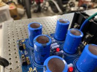
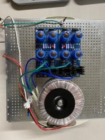
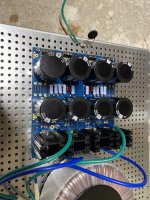
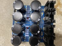
I'm in the process of building a pair of F5T v3 monos and built the power supplies using PSU from the diyaudiostore. I've had one of the PSUs assembled and running for about a week and upon inspecting it today, noticed the capacitors were bulging/leaking. I assume there's a mismatch between the capacitors and transformer, but I'm not certain. Any ideas what would cause this to happen?
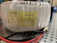
1. Transformer - AN-6224 (1x)
2. Capacitors - 25V/22,000uF (8x)
Thanks in advance!
I'm in the process of building a pair of F5T v3 monos and built the power supplies using PSU from the diyaudiostore. I've had one of the PSUs assembled and running for about a week and upon inspecting it today, noticed the capacitors were bulging/leaking. I assume there's a mismatch between the capacitors and transformer, but I'm not certain. Any ideas what would cause this to happen?
1. Transformer - AN-6224 (1x)
2. Capacitors - 25V/22,000uF (8x)
Thanks in advance!
Attachments
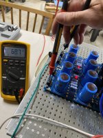
You are over-voltaging your caps. Rating on the caps is 25VDC. Using a 24VAC secondary after rectification will be about 34VDC. That looks to be what are measuring with a total potential difference of 68VDC from V+ to V-. (34 Volts per rail).
Those caps need to be replaced with higher voltage rating or go down to a x-former w/ 18V secondaries. Given this is the F5T, I'm guessing you want to keep the 34VDC rails so higher rated caps.
In the meantime, I recommend powering it down and not turning it on until the caps are replaced.
Those caps need to be replaced with higher voltage rating or go down to a x-former w/ 18V secondaries. Given this is the F5T, I'm guessing you want to keep the 34VDC rails so higher rated caps.
In the meantime, I recommend powering it down and not turning it on until the caps are replaced.

Thanks for the quick reply. If I replaced it with 35V caps is that enough headroom or would 40V be better? Also, is the capacitance okay (22,000uF) or should I increase that as well?You are over-voltaging your caps. Rating on the caps is 25VDC. Using a 24VAC secondary after rectification will be about 34VDC. That looks to be what are measuring with a total potential difference of 68VDC from V+ to V-. (34 Volts per rail).
Those caps need to be replaced with higher voltage rating or go down to a x-former w/ 18V secondaries. Given this is the F5T, I'm guessing you want to keep the 34VDC rails so higher rated caps.
In the meantime, I recommend powering it down and not turning it on until the caps are replaced.
35V will work just fine.
Longer life and ability to experiment with higher rail voltages, go with higher.
For my F6 mono-blocks, +/-24V rails, I'm installing some 50V 18kuF caps rated for 8k hours. The PSUs will probably outlast me.
For the actual Farad value, NP recommendation is 10-15kuF each. As it is Class A, bigger Farads aren't necessarily better as current draw is steady. I believe the larger Farad bank will help with filtering but haven't sat down w/ an o-scope to compare nor run thru the theoretical calculations.
Go with what you can afford. Bare minimum is 35V, 10kuF and will work perfectly fine. Of course, overkill works just fine too. Just make sure you have a way to control the in-rush current on power-up.
Much appreciated. A quick look at the usual sources have 40V/22KuF capacitor options that are ~$20 each. Crazy expensive when I need 16. I was only looking at 22KuF and above, so I'll play around with the filters some more. I used a soft start in my F6 build and plan on doing the same for these, so in rush should be covered.
These are the ones I bought: https://www.mouser.com/ProductDetai.../381LL183M050A062?qs=Cb2nCFKsA8pf5Xbf2Z56ZQ==
I talked myself into them, reasoning I never wanted to touch the PSUs again.
I talked myself into them, reasoning I never wanted to touch the PSUs again.
Ugh. Its costs like these that keep me interested in the used market vs building.These are the ones I bought: https://www.mouser.com/ProductDetail/Cornell-Dubilier-CDE/381LL183M050A062?qs=Cb2nCFKsA8pf5Xbf2Z56ZQ==
I talked myself into them, reasoning I never wanted to touch the PSUs again.
Could get some 35VDC ones for as little as $3.09 a pop.
https://www.mouser.com/ProductDetail/KEMET/ELH109M035AR4AA?qs=KFnARfWiB%2BvWpvYfXjTF3A==
It is all about how crazy you want to get.
https://www.mouser.com/ProductDetail/KEMET/ELH109M035AR4AA?qs=KFnARfWiB%2BvWpvYfXjTF3A==
It is all about how crazy you want to get.
edwinjones4 is building monoblocks so there is a huge extra cost. Power supply and chassis with heat sinks are a large part (much more than 50%) of the cost of Class A amplifiers.
DIY is probably less expensive than buying factory produced used, and equivalent monoblocks used are probably very hard to find.
DIY is probably less expensive than buying factory produced used, and equivalent monoblocks used are probably very hard to find.
6sX7 created a monster…
I settled on 50v/15kuF which split the difference between my original/undersized capacitors and the most expensive option available. Now I have to spend the next hour desoldering the old capacitors from my PSUs.
https://www.digikey.com/en/products/detail/cornell-dubilier-electronics-cde/381LX153M050A052/1700316
Going to be fun times! Especially when you get the new ones in and get things back up and running. Very glad they didn't burst on you. Nasty stuff.
The Apex Jr. capacitors are a fantastic deal at $3.99, I have a set and am very happy with them. I figure if Nelson uses 15,000uF in the factory build Firstwatt amps, it's a perfectly reasonable value. It also says 15,000uF on the schematic. 
https://www.apexjr.com/capacitorsR.html
https://www.apexjr.com/capacitorsR.html
Ah. I’m tempted to buy a bunch just to have for future projects.The Apex Jr. capacitors are a fantastic deal at $3.99, I have a set and am very happy with them. I figure if Nelson uses 15,000uF in the factory build Firstwatt amps, it's a perfectly reasonable value. It also says 15,000uF on the schematic.
https://www.apexjr.com/capacitorsR.html
I got distracted looking for the voltage and missed the farad value in the BOM.
P.S. the links to the schematic and BOM are working in the store but are broken in your first post.
good board that is laid out for CRC?
…
positions for 35-40mm caps and resistors, bleeders and maybe an LED or two. 🙂
Even though there‘s no spot for bleeders, I‘d recommend ZM‘s „HA!“ board. https://www.diyaudio.com/community/threads/old-soul-old-soul-bip-kit-packages.372978/
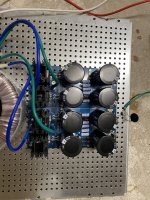
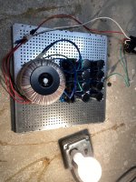
explicative Just got my 50v/15,000uF caps today and put them in my psu. After consecutive 5A blown fuses after startup, I added the dim bulb tester to see if there was a short - it lit up like a christmas tree. Any idea what I've done wrong? All else has remained the same from my previous post (#1,842).
600va PSU
8x 50v/15,000uF capacitor
5A fuse
600va PSU
8x 50v/15,000uF capacitor
5A fuse
Attachments
Is this with a soft-start circuit in place?
If not, guessing in-rush current.
Might be worth posting a close-up of the boards showing the solder joints, both on top and bottom.
If not, guessing in-rush current.
Might be worth posting a close-up of the boards showing the solder joints, both on top and bottom.
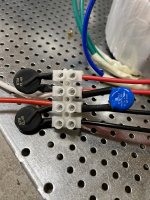
No soft start board yet...just the CL60's in series. Here are a few more close up pics of the solder pads. I did notice one of the new capacitor leads was touching the metal baseplate during the initial startup, but I've since trimmed everything.
Attachments
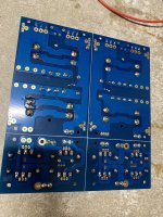
Looking at the pictures, nothing pops out.
Have you tried powering up one rail at a time to see if it can be isolated more?
I haven't used the rectifier boards. Double check the primary and secondary connections?
Have you tried powering up one rail at a time to see if it can be isolated more?
I haven't used the rectifier boards. Double check the primary and secondary connections?
.....I did notice one of the new capacitor leads was touching the metal baseplate during the initial startup, but I've since trimmed everything.
That could do it - a short to ground.
- Home
- Amplifiers
- Power Supplies
- diyAudio Power Supply Circuit Board v3 illustrated build guide