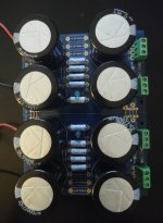
Powered it up and nothing is smoking or sparking. V+ to GND is 25.72 V and V- to GRD is -25.60 V.
I did go back and touch up all the solder joints, I appreciate the constructive criticism on that.
Are there any other tests that can be done at this point? Now I’m just waiting on amp boards.
I did go back and touch up all the solder joints, I appreciate the constructive criticism on that.
Are there any other tests that can be done at this point? Now I’m just waiting on amp boards.
Nice!Powered it up and nothing is smoking or sparking. V+ to GND is 25.72 V and V- to GRD is -25.60 V.
It's amazing what shows up when zoomed into a photo. I use my phone camera to inspect boards. I can't see well enough without magnification. 😀I did go back and touch up all the solder joints, I appreciate the constructive criticism on that.
Not really. It seems that it is working as it should. If you have the gear, you could have some fun and measure the ripple. However, it's definitely not a required test.Are there any other tests that can be done at this point? Now I’m just waiting on amp boards.
Hi all
Hope this is the right place to post.
I am having trouble with my F5 that has died since being at a friends. It uses the V3 PSU.
I have had it running for a bit over 18 months and all was good. Now it had come back dead. No LEDs on the PSU and no voltage at PSU filter board outputs V+ V- GND.
I have voltage at the transformer and the DC outputs of bridge rectifier when filter board not connected. When connected no voltage at D+1 D-1 D+2 D-2
I have pulled the filter board out of the chassis to test but I am only a dumb sparky and with caps etc in circuit the ohm readings are a little funny. Can see some resistances rise obv going through the caps.
Everything looks ok on the filter board but I still can't get it to power on even with amp boards disconnected.
I guess something has gone wrong with the amp boards but just starting at the beginning and im up to the filter board.
Any help greatly appreciated.
Thanks
New site/forum is great
Attachments
Ben Mah, on the previous page, recommended a test for me when I had just finished my board. Maybe that would help rule out a short on the board?
Thank youBen Mah, on the previous page, recommended a test for me when I had just finished my board. Maybe that would help rule out a short on the board?
I found his post
Set your multimeter to measure resistance, no power to power supply, black probe to Ground, red probe to V+, there should be resistance measured.
Black probe to V-, red probe to Ground, there should be resistance measured.
Yeah both have rising resistance which is what I saw before.
the rising resistance should be your caps charging.
As Ben pointed out, could be a solder joint or trace gone bad. Occum's razor points to a solder joint of the two. Pictures of the underside would help. The ones on top look bone dry but I know some folks don't flow the solder all the way thru and on both sides.
As Ben pointed out, could be a solder joint or trace gone bad. Occum's razor points to a solder joint of the two. Pictures of the underside would help. The ones on top look bone dry but I know some folks don't flow the solder all the way thru and on both sides.
If I were to use this to replace a GFA-555 power supply with 100V caps and 83-85V rails, would the resistance need to change?
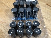
I'm re-spec'ing my PS for balanced monoblocks operation of a 1stW clone. Went a wee bit overboard with the caps...
50 VDC
144000 uF
105 C
8000 hrs
18 mOhm ESR
I'm hoping they last my lifetime.
50 VDC
144000 uF
105 C
8000 hrs
18 mOhm ESR
I'm hoping they last my lifetime.
Attachments
Last edited:
I ordered a ton of the 3 watt 0.47 ohm resistors. My Aleph J build calls for 4 per side (8 total)...any reason NOT to fill all 7 positions per side (14 total)? For R1-R8 and R Optional 1-6 if anyone is looking at the BOM. If a total waste I will pass.
And yes, been away for a few months and getting back into it. Away for Christmas, work was busy, now back to building!
And yes, been away for a few months and getting back into it. Away for Christmas, work was busy, now back to building!
As the resistors are in parallel, filling all spots will effectively reduce the filtering, allowing more ripple.
Ohhh, so I should just leave it be with the suggested (4 per side). I know 'more is better' isn't always true 🙂
I wouldn't alter the circuit unless you needed extra current capability. If you do, then new values would need to be calculated to match, which, if I track your original post, defeats your purpose.
Yup, agree. Will leave as-is. I trust the people much smarter than me on this stuff, I am just a 'builder' not a designer or engineer.
Yah, I'm also curious to the relationship between resistance between the parallel banks and rail voltage. Does it require modelling to calculate the resistance? Does anyone have a PSU Designer II template for this board?
Last edited:
what do you mean by "modelling", the amount of ripple expected? Or just what the resistor bank equates to, 1/R_t = 1/R_1 + 1/R_2 + 1/R_3 + ... + 1/R_n.Yah, I'm also curious to the relationship between resistance between the parallel banks and rail voltage. Does it require modelling to calculate the resistance? Does anyone have a PSU Designer II template for this board?
Its a CRC filter correct? I don't know the correct resistive value to be used between the filter banks for a given voltage.
There is no "correct" value based simply based on the supply's output DC voltage. You can model the entire PSU and see what value provides the 'lowest' simulated ripple for the PSU with your choice of components through to the load. Everything has a small impact. It might be fun to see what has the most impact, and where the laws of diminishing returns kicks in for your personal tastes.
FYI, the diyaudiostore universal PS boards are expected to be available again sometime in April or May based on a response I received from support.
Speaking of which, anyone know of a good place to buy a board that is laid out for CRC? I'm using bridges, so I don't need the rectification section. Just positions for 35-40mm caps and resistors, bleeders and maybe an LED or two. 🙂
Maybe something like this? https://jimsaudio.com/super-heavy-duty-crc-clc-power-supply-pcb/
Maybe something like this? https://jimsaudio.com/super-heavy-duty-crc-clc-power-supply-pcb/
Last edited:
- Home
- Amplifiers
- Power Supplies
- diyAudio Power Supply Circuit Board v3 illustrated build guide