But if you don't understand what is going on and you are just connecting wires, you should follow the instructions exactly. You are dealing with live electricity and mistakes may be deadly.
A very good thing when you’re done (ready to power up that thing) is to use the light bulb tester... https://www.diyaudio.com/forums/power-supplies/167579-light-bulb-tester.html#post2519267
I understand most of whats going on and can read the schematics. I did a good chunk of electronics in a physics degree but that was a long time ago. So I'm a little rusty on some aspects.
I powered up with a VARIAC with a 5A fuse and slowly raised voltage from 1 to 5 to 20 and up to 120. Everything worked fine. No smoke. LEDs got brighter as I increased the voltage. All readings were as expected.
All safety precautions were taken.
I should have mentioned the secondaries were also paired up before I tested the power.
So I had:
LIVE ==> RED A
NEUTRAL ==> BLACK A
...and everything went fine.
I just changed the setup to how you suggest which is the same as the image supplied by AllInMyHead:
LIVE ==> RED A
NEUTRAL ==> BLACK B
...and the output was the same as my initial wiring.
Your connection of live to Red A and neutral to Black A was definitely incorrect. You got lucky when you powered it up and nothing catastrophic happened.
You should not power up a circuit when you know that it is not correctly wired.
You should not power up a circuit when you know that it is not correctly wired.
Attachments
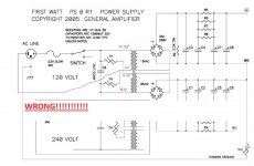
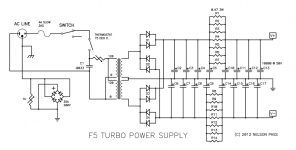
ok. I think I see where the confusion is coming from. I'm looking at the PSU from the F5T article by Nelson Pass.
You can see that the two primary blacks are connected to C1. But there is no thermistor. In 6L6 build guide there is which is the same as the F5 as you point out.
That's what I missed.

I'm not sure I got lucky though. Since the thermistor is an inrush current limiter, and since I did a gradual increase over a good period of time, its resistance decreased and had (essentially) the same effect as simply being a wire connecting the two blacks. And that's why my PSU worked and didn't fail when turning the power on.
If I went from 0V to 120V then there could have been a problem.
I've fixed my build now accordingly so thanks for taking the time to help me out.
You can see that the two primary blacks are connected to C1. But there is no thermistor. In 6L6 build guide there is which is the same as the F5 as you point out.
That's what I missed.
I'm not sure I got lucky though. Since the thermistor is an inrush current limiter, and since I did a gradual increase over a good period of time, its resistance decreased and had (essentially) the same effect as simply being a wire connecting the two blacks. And that's why my PSU worked and didn't fail when turning the power on.
If I went from 0V to 120V then there could have been a problem.
I've fixed my build now accordingly so thanks for taking the time to help me out.
Attachments
Silly question: has anyone done anything interesting with the current from the transformer bolt? Or ist dat verboten fur fear of die meltenboomensmokenspitzen? I thought I might use it for das blinkenlights or something.
drats.
I've noticed antek are out of 300VA 18V and 400VA 18V traffos. Is there another good supplier of shielded transformers in the US? I'm open to picking up the 500VA or 600VA ones instead but they're just bigger and heavier. I was thinking of going dual-mono.
I've noticed antek are out of 300VA 18V and 400VA 18V traffos. Is there another good supplier of shielded transformers in the US? I'm open to picking up the 500VA or 600VA ones instead but they're just bigger and heavier. I was thinking of going dual-mono.
I haven't purchased transformers from them, but Toroid Company in MD is showing a few in stock. They've been wonderful to deal with for some mounts I purchased FWIW. Their staff seems very knowledgeable re: transformer requirements for various applications. I'd recommend giving them a ring.
https://toroid.com/sku/738.182/
https://toroid.com/sku/738.182/
Or AS-2220? Right Jim? For dual-mono? 200VA... (They are in stock) —Used them in M2X monoblocks. Easily ended up with 24VDC+/- rails (26 and change if I recall)...
Last edited:
Dual mono in the same chassis? I.E., how to make your amplifier really, really heavy?
Yes, the 200VA would be more than enough for one channel.
Yes, the 200VA would be more than enough for one channel.
Silly question: has anyone done anything interesting with the current from the transformer bolt? Or ist dat verboten fur fear of die meltenboomensmokenspitzen? I thought I might use it for das blinkenlights or something.
Oh well... if I had, I would answer in plain broadest swissgerman [emoji23]
drats.
I've noticed antek are out of 300VA 18V and 400VA 18V traffos. Is there another good supplier of shielded transformers in the US? I'm open to picking up the 500VA or 600VA ones instead but they're just bigger and heavier. I was thinking of going dual-mono.
Antek (as of today) is showing 18 volt transformers back in stock, 200, 300, and 400 VA. I had emailed the sales department a while ago and they indicated they would have them the week of Aug 10th.
For R20 and R21 (LED dropping resistors), the BOM says value should be 4.7K - 10K. The specified part (digikey S10KQCT-ND) value is 10k. Is that the right choice, assuming the LED specified in the BOM (digikey 751-1139-ND)?
Intended for an AJ, transformer will be Antek 3220 (300VA, 20V), bridges instead of discrete diodes.
Also, BOM says red or green LED -- do most folks do different color for each side?
Intended for an AJ, transformer will be Antek 3220 (300VA, 20V), bridges instead of discrete diodes.
Also, BOM says red or green LED -- do most folks do different color for each side?
LED brightness is controlled by that resistor, nothing more. More ohms = dimmer.
LED Calculator - Current limiting resistor calculator for LED arrays
Shoot for 2-3mA at most with modern clear LED unless you want them really bright.
3220 will work perfectly.
Use whatever you want. You can get pink and purple these days, pink is actually really neat.
LED Calculator - Current limiting resistor calculator for LED arrays
Shoot for 2-3mA at most with modern clear LED unless you want them really bright.
3220 will work perfectly.
Use whatever you want. You can get pink and purple these days, pink is actually really neat.
Hi. I will be building M2X as my first FW clone after the ACA. I read half of this thread to prepare for the PSU, and I think I am ready to make my choices.
Though I have one question about the Inrush Current Limiter (ICL). NP is using just one CL-60 on the 230V supply schematic for that, but the honourable AndrewT was commenting several times that it's not enough, and at least 2 CL-60 should be used in series on 230V live line, but something of 60-80 ohms "cold" resistance would be preferable (2 CL-60 have about 22 ohms).
I found this ICL that I would like to use (75 ohms), but could some experts comment if that is ok, or are there some reasons that I do not know that makes this choice unsuitable for his application.
MS22 75004
My other choices are as below. I tried to be concervative as I am more of the "enough is enough" type than "more of good is better". Again, if someone would care to comment, I would appreatiate it very much (this is my first sourcing of the parts):
300VA 230V-2x18V Toroidy transformer;
Monolithic bridge rectifiers 200V 35A (saves space on my 4U/300 chassis, easier and cheaper);
No optional PI resistors (8 in total);
No input nor output snubbers (no need for class A amplifier);
18000uF 50V capacitors (we all want to be a tiny bit smarter than Papa, don't we?);
2.4k bleeder resistor;
3300pF line X1 rated capacitor and ICL (as above);
CL-60 on the audio ground to "float" it.
And another small question: if I want to have 2 blue LEDs on the front pannel, where is the best place to wire them from? I would want to keep PSU LEDs as they are, as I consider them being a safety warnings.
Thanks to everyone who will be kind to comment!
Last edited:
R11, 12, C17, 18 are the output snubber. Leave open.
Cx1, Cs1, Rs1 and Cx2, Cs2, Rs2 are the input snubbers and are quite helpful, though not required. Go to the Quasimodo results thread and see if you can find your transformer's values there.
Why leave r11,12,c17,18 open? I have used the Quasimodo solution.
Just trying to learn....thanks!
Diagnosing Problem
Hi all, I am a first time poster. I am building an F6 with DIYaudio boards, the DIYAudio PSU and the 4U deluxe chassis. I could use a little help diagnosing a PSU problem.
For the transformer, Antek was out of the 300va and 400 va transformers, so I bought a 500va transformer with dual 18v secondaries. I figured overkill on the transformer is ok. I built the PSU with TO3 diodes, and separated the diodes from the capacitor bank to fit the chassis better. I've triple checked the wiring and I believe it is correct from the mains to the transformer, and transformer to the diodes.
When I powered up the power supply (initially w/o the CL-60 to chassis ground) - everything seemed fine. The voltages were +25 and -25 measured from the PSU ground. Also, 18V ac to both sets of diodes.
When I installed the CL-60 to chassis ground, and powered things up on a dim bulb tester, the bulb lit up and the thermistor got hot quick. I took the thermistor out and measured the PSU voltages to chassis ground and found 11V between PSU ground and the chassis. The other voltages are +36 and -14 from the PSU +/- rails to chassis.
Are there any obvious things to check? If I leave the PSU floating from the chassis everything seems normal, but obviously that is not an ok solution. I can post pictures if that helps.
One additional question - I think I correctly identified the transformer primaries - A120, A0, B120, B0. But does it matter which set of primaries (both red/black) are A vs B? Also does it matter which secondaries (both blue/green) go to which rectifier bank?
Thanks in advance.
bmdduck
It sounds like you have something electrical that is in contact with the chassis.
Does the transformer have any other secondaries and do you have other power supplies in the chassis?
Is only the power supply connected with no amplifier boards connected?
One thing you can do is with the PSU floating and the power off, check for continuity between various points of the power supply and chassis. Something must be putting 11V into the chassis.
Clear, well lit, high definition pictures would definitely be helpful.
- Home
- Amplifiers
- Power Supplies
- diyAudio Power Supply Circuit Board v3 illustrated build guide