Hello, I'm wondering about heat sink size for the Honey Badger. I have a chassis with two heat sinks, each 300mm x 100mm with 40mm fins. Will this be adequate for a stereo build? Thanks!
those should be plenty adequate for any reasonable home listening, with voltages up to ~+/-65Vdc and normal bias setting. If you are going for a consistent 4-ohm load, I would reduce voltage to +/-55Vdc - not because of the heatsink, but more so because of HBs 3-pr of outputs.

Hi All,
I finally reached the test phase of my Honey Badger build. I have bias set to 30mV between TP1 and TP2. DC offset is 1mV or less. Voltage drop across R14 is 8.25v. Hooking up my signal gen at full blast I'm only getting around 60mV rms on my scope with resistors. I hooked up my tablet and at full volume I can't hear anything through my test speakers. The Main In connections do have the grounds tired together if that matters.
Does this need a voltage gains stage before it? Is something wrong? I also have a Mezmerize buffer that I plan to use but it is not hooked up for these tests. I fully expected the tablet to get quite loud. I have an Amp Camp Amp and it just has a phone without a preamp that gets loud for what it is. Any Ideas where to start looking?
Shawn
Attachments


Hi,
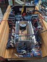
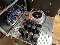
Attaching the power devices via connectors (if I interpret your pics correctly) literally cries for oscillations. You need to solder all six transistors to the PCB, as the build guard says.
Best regards!
Attaching the power devices via connectors (if I interpret your pics correctly) literally cries for oscillations. You need to solder all six transistors to the PCB, as the build guard says.
Best regards!
Or move the base/gate resistors from the PCB to the pins of the devices.Attaching the power devices via connectors (if I interpret your pics correctly) literally cries for oscillations. You need to solder all six transistors to the PCB, as the build guard says.
Just observing, in the 2nd photo on post 2784, there is a 0.22 ohm source resistor that looks like it flamed. Hard to tell with the picture angle.
Like others have already mentioned I would be cautious of long leads from the PCB to the output transistors as it can produce an oscillator. I also note that the bus bar appears to be close to the bent leads of the output transistors which in and of themselves have wires twisted on the leads. Hard to see with the viewing angles provided, but a possibility for potential shorts. Your fuses haven't blown, you have bias set, and you have a low DC offset so double check that the input signal is getting to where it needs to go and trace it. You might have a cold solder joint somewhere where the AC signal is passing through. You can use a signal generator set to a low voltage, say 100mV RMS and follow along with your oscilloscope. Alternatively, you can use an AC RMS voltmeter using the schematic as your guide. Post 2160 by member stuartmp I believe has the updated schematic.
Good luck!
Best,
Anand.
No, not for digital sources. It has a closed loop gain of ~ 28dB or thereabouts. For analog, of course they have phonostages with gain.Does this need a voltage gains stage before it?
Most likely if the amplifier isn't well...amplifying 😉 .Is something wrong?
Like others have already mentioned I would be cautious of long leads from the PCB to the output transistors as it can produce an oscillator. I also note that the bus bar appears to be close to the bent leads of the output transistors which in and of themselves have wires twisted on the leads. Hard to see with the viewing angles provided, but a possibility for potential shorts. Your fuses haven't blown, you have bias set, and you have a low DC offset so double check that the input signal is getting to where it needs to go and trace it. You might have a cold solder joint somewhere where the AC signal is passing through. You can use a signal generator set to a low voltage, say 100mV RMS and follow along with your oscilloscope. Alternatively, you can use an AC RMS voltmeter using the schematic as your guide. Post 2160 by member stuartmp I believe has the updated schematic.
Good luck!
Best,
Anand.
Last edited:
I went back and read through many pages and realized my is something wrong question is quite stupid. I initially powered this up on my dbt missing a .68uf cap and a 15ohm resistor. I do not have a 15 so I used a 18ohm. I'll remove connectors and see how I can solder the power transistors as close as possible to the board. Really not trying to buy all new transistors to mount right on the board
I do have signal through the input cap but didn't trace farther than that. At this point I'll rework the transistors before I waste any time signal tracing.
I do have signal through the input cap but didn't trace farther than that. At this point I'll rework the transistors before I waste any time signal tracing.
Well pick it apart. What don't you like? I knew the flying leads would be controversial but I have Kenwood Basic M2a to repair and it uses flying leads. No connectors but power transistors mounted to heat sinks wired to the board. Mine is in the test phase with the buffer not even connected yet.
I would be removing the board from the heatsink and test it without the outputs installed driving no load.Any Ideas where to start looking?
There are some major issues going on there and not many things are followed recommended amplifier building practices.
Please have a look at my build album for some guidance.
I have a question about the resistors to put in series with the VCC rails during biasing.
Instructions in the Build Guide say to replace the fuses with 10R resistors when adjusting R17, R7 & R30. But there's already 22R resistors (R53 & R54) in parallel with the fuses.
So, were the instructions to replace the fuses with 10R resistors written for a board with R53 & R54 not populated?
Or, should I replace the fuses with 10R resistors, giving me 6.88R in series with VCC when biasing?
Thanks!
The resistors are there for if there is a problem when first started. As you noted, they are in parallel with the fuses. This means for the fuse to burn, it has to get the resistor hot enough to smoke it first, then the fuse will blow. In my personal experience, they create a problem if left in while operasting. You also will not get a true bias reading if you adjust it with them installed. I would start it with the resisitors installed, dial up the bias, if there are no issues, dial bias back down, remove resistors, install fuses, adjust bias for final time, and enjoy your new amp.
I smoked an output device because the resistor was left in. No guarantee the fuse would have saved it, but no chance at all with a resistor in parallel.
I smoked an output device because the resistor was left in. No guarantee the fuse would have saved it, but no chance at all with a resistor in parallel.
After thinking about the fuse and resistor, I got the order of smoking reversed. The fuse would burn first (because it has lower resistance, the current would be taking the fuse path), but current would flow through the resistor, after the fuse blows, until it gets hot enough to burn-up, literally.
Well, I blew up the second channel. My fault for not using a dim bulb tester. Turned it on and R53 and 54 turned into LEDs. Im pretty sure what happened is I changed out C1 with a nice poly cap and forgot to trim the leads and it probably was long enough to touch the heat sink. Can’t see anything else to cause it. Testing all the output devices I get continuity across all the pins so those are probably fried. Hopefully have replacements tomorrow.
C1 is the input cap, the leads touching the heatsink would not cause issues unless it curled back and touched something. You have a different issue. Did you check, before powering, that none of the leads of the output transistors had continuity with the heatsink? To pull that much current, you had a dead short.
- Home
- Amplifiers
- Solid State
- diyAB Amp - The "Honey Badger"