Alex, that PCB looks good, but the diyAudio PCB needs to work with heatsinks already drilled for a different project to meet the goals set forth at the beginning.
It stinks OS is unable to give his final sign of approval on the board, but he has been inactive since 10/2011. I agree it is time to move on, especially since the PCB design seems to be complete except for some small details.
It stinks OS is unable to give his final sign of approval on the board, but he has been inactive since 10/2011. I agree it is time to move on, especially since the PCB design seems to be complete except for some small details.
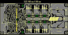
...... I layout this rev 1.8 and ask you what's wrong with PCB ? Size only 190 mm X 88 mm . I can also modify OS PCB for us in better shape ......😉
Alex.
Nice PCB Alex, way to go!

...... I layout this rev 1.8 and ask you what's wrong with PCB ? Size only 190 mm X 88 mm . I can also modify OS PCB for us in better shape ......😉
Alex.
nice layout, users of Conrad Engineering hatsinks will find this layout very useful...
+1. We will move forward ASAP on getting the boards - That I promise..
Alex, that PCB looks good, but the diyAudio PCB needs to work with heatsinks already drilled for a different project to meet the goals set forth at the beginning.
It stinks OS is unable to give his final sign of approval on the board, but he has been inactive since 10/2011. I agree it is time to move on, especially since the PCB design seems to be complete except for some small details.
...... I layout this rev 1.8 and ask you what's wrong with PCB ? Size only 190 mm X 88 mm . I can also modify OS PCB for us in better shape ......😉
Alex.
love that alex mm is here for us . his pcb design work just amazes me !!!! however i do question all the heat from the outputs so tightly together .
cheers Woody
imho, having those power trannies close together means they will track each other better, not a bad thing......especially when using conrad engineering heatsinks....
Conrad Heatsinks - Products
Conrad Heatsinks - Products
Alex, the decision to put the rails both on one side of the board, instead of wrapping around it was made for a reason. Furthermore, the feedback point is at not at the output terminal where it should be. OS's board was very carefully designed. Do not underestimate OS's work.
- keantoken
- keantoken
Hi Andrew,
I remember that it was you who influenced OS to put the rails together. IMO a wise decision. If one wonder, just look back in the thread.
My
The layout could perhaps be even better while keeping the OS style layout. If we look at the PS section, loop area could be smaller. The cap closest to output section could feed BJT's furthest away and vise verse...
I think the ask of Alex is, could he take OS's PCB and correct the output spacing to conform with the standard DIYA spacing. Not sure if someone can provide the exact requirements?
I think Alex or someone else should open a parallel thread to do this.
Something like "Clone DIYA amp - a different approach".
Regards,
Max.
Something like "Clone DIYA amp - a different approach".
Regards,
Max.
Whazz all the fuzz about Alex's board, he's learning still but in the right direction. 
What we want from a PCB in audio is minimal degradation in bandwidth domain. Tracks current capability is not an issue, correct layout organization of the parts on the PCB and PCB itself as major part here and its sum of all parasitic influences to all parts is the biggest problem and what PCB designer has to have all the time in front of himself. Theoretically calculated frequency compensations resulting in no change on finished PCB will tell us the board is fine. New problems arising (oscillations, hum, noise, etc) when putting an amp into action will tell us, although too late but nevertheless, the PCB is falsely designed.
What we want from a PCB in audio is minimal degradation in bandwidth domain. Tracks current capability is not an issue, correct layout organization of the parts on the PCB and PCB itself as major part here and its sum of all parasitic influences to all parts is the biggest problem and what PCB designer has to have all the time in front of himself. Theoretically calculated frequency compensations resulting in no change on finished PCB will tell us the board is fine. New problems arising (oscillations, hum, noise, etc) when putting an amp into action will tell us, although too late but nevertheless, the PCB is falsely designed.
Alex, the decision to put the rails both on one side of the board, instead of wrapping around it was made for a reason. Furthermore, the feedback point is at not at the output terminal where it should be. OS's board was very carefully designed. Do not underestimate OS's work.
- keantoken
in this case, just move the output pin closer to the feedback point and we're done.....me, i put the output coils at the binding posts anyway......
I think it's okay to fix pin spacings, why not? But the basic layout should not be compromised. If you want a different board, then by all means etch it yourself. But to jump in when OS is not here and suddenly try to change the design when he cannot add his input, is totally ridiculous and unfair. You should have discussed it with him when he was making the decisions, when there was a level playing ground.
I'm with Kean and AndrewT
I've followed this thread quietly from the get-go, but lots of people poured time into this project and Variac was already working with OS to bring the boards to market.
Most of the sweat has come from OS and he built more than just one version with good results. I agree, out of respect to him, let's stick with what he has put into this.
My vote is that this is no time for scope creep and involving interested parties in another debate for the next few months.
Tweak the boards so they meet the standards and then let Variac take it from there. That's my 2 cents! 😉
Nice P.C.B. Mr. Alex , PCB REV 1.8 ,Where are The B.O.M. and schematic for this PCB .Can you post PCB. ,layout ,circuit,in pdf files Thanking
Vedmitra Sharma
Vedmitra Sharma
That was then, this is now
I had the pleasure visiting one afternoon with OStripper when he was still in TN. I listened to the several editions of amps he had at that time. I found out in a hurry I was no match, not even in the same league wrt the finer points of amps. I also found OS to have considered everything. He spoke of the years he spent as a bench tech repairing gear and the solutions (configurations) found to be most effective. Pete was so enthusiastic to share what he was working on. It was one of those encounters you leave with a headache.
Send the board out for verification before committing to a bulk run. Be sure to leave OStripper's mark on it.
what ever happened to the evaluation of Ostripper's board design supposedly done by jojod?
afaik, it was a sucsess so the next step should have been board fabrication so what happened next?
afaik, it was a sucsess so the next step should have been board fabrication so what happened next?
- Home
- Amplifiers
- Solid State
- diyAB Amp - The "Honey Badger"