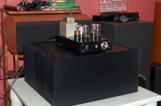
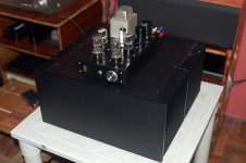
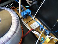
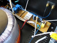
This is the DA prototype build which has been tortured for the past 2 months. It only runs at about ~60mA per device since my converted bench top power supply has a limited headroom. It shall be retrofitted with a monstrous power supply and push the bias to OS's recommended upper limit. Also, the inclusion of a soft start circuit and a speaker turn-on delay and dc protection circuit.
J
J
Attachments
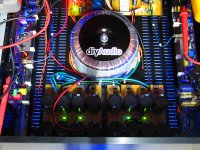
running the "big" ccs of the VAS at ~11mA and I get a stable 56-57*C temp on the small heatsink for Q10, Q11, and Q12.
trying the "finger" test and it kinda stings if I try to touch it for 5 seconds. kinda hot for my taste.
planning to reduce ccs current to about 8mA. any experience in running devices this hot for prolonged periods? I'm just worried about the device longevity or do I just worry too much?
trying the "finger" test and it kinda stings if I try to touch it for 5 seconds. kinda hot for my taste.
planning to reduce ccs current to about 8mA. any experience in running devices this hot for prolonged periods? I'm just worried about the device longevity or do I just worry too much?
OS put his designs through extensive testing as I recall. There are many examples of test equipment throughout the years that ran their transistors hot and have survived a long time.
running the "big" ccs of the VAS at ~11mA and I get a stable 56-57*C temp on the small heatsink for Q10, Q11, and Q12.
trying the "finger" test and it kinda stings if I try to touch it for 5 seconds. kinda hot for my taste.
planning to reduce ccs current to about 8mA. any experience in running devices this hot for prolonged periods? I'm just worried about the device longevity or do I just worry too much?
if you have a distortion meter, you can measure the effect of lowering CCS current to 8mA, i feel there is no harm in that....
Hi,
I think OS choose high VAS current because of the 2ef topology. In order to the keep distorsion low into low impedances he wanted high VAS current. I recall he mentioned this somewhere earlier in this thread.
Measure distorsion into severeal different impedances with high and low VAS current. Differences?
Why not increase cooling instead?
even in the lo-tim amp, leach lowered the VAS current a bit to address some heat issues....triple darlington output stages wherein current gain is very very high can use 5mA in the VAS....
I guess I'm sticking with 11ma for the VAS at the moment, been playing all day long now and still holding at 59*C. I'm running the outputs stable at 100mA.
I've opened one a long time ago and also aware of those high current VAS but I'm more concerned with the temp readings on this amp. So far she's been a dear all day long.
the Ampzilla's used TO-66 devices, not sure if still available, on bigger heatsinks, that is why they can operate that way...
the Ampzilla's used TO-66 devices, not sure if still available, on bigger heatsinks, that is why they can operate that way...
Yup I remember they used TO-66 devices, not to mention some devices that are "proprietary" GAS devices.
And most of all, I remember it to really, really sound great like the DA Class AB prototype.
Attachments
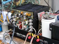
yes, the output trannies are as i recalled, 2n3773/2n6609 types, the ic biasing chip was a CA3046.....http://www.intersil.com/data/fn/fn341.pdf
Still have a sharp memory, me I only recall the great sound it made.
I think I only installed a soft start in there and fixed some minor issues too but nothing more.
I think I only installed a soft start in there and fixed some minor issues too but nothing more.
OT: back in those days i was asked to decode the ic used....so happened i was working in a semiconductor firm maintaining K&S wire bonders....the control board used such ic and we had a lot of spares.....guess i was lucky.....😀
how is the sound compared to say a leach?
As I have Prof. Leach's Low TIM version, I think I would say that the Honey Badger (that's our nickname for it at DA Central) has more control of the lows and is somewhat extended in the highs but not that tiring (I didn't even used the lead compensation cap).
The Low TIM is a great amp, excellent numbers during measurement. My only qualm with it is it doesn't seem to go low enough, don't get it wrong though, it's capable of a lot of bass but it kinda rolls off quite too early for my ears.
Imho, the Honey Badger is in it's class, a well balanced amp, it behaves well even with low impedance loads and performs right as intended. Overall sonic presentation is excellent. Any amp builder, diyer, amp collector, student and what have you will surely enjoy building this and be rewarded afterwards by being able to listen to a wonderful amp that can give commercial amps costing many times more a run for their money.
Cheers
I know
this is thread for AB
but
did anybody tried to run this circuit in AC? http://www.tubecad.com/2009/11/12/class-ac 590ma idle current.png
OPS will have MUCH less distortion...😉
this is thread for AB
but
did anybody tried to run this circuit in AC? http://www.tubecad.com/2009/11/12/class-ac 590ma idle current.png
OPS will have MUCH less distortion...😉
- Home
- Amplifiers
- Solid State
- diyAB Amp - The "Honey Badger"