The cascode I suggested is actually proposed to me by Cordell in his book thread.
"I normally recommend caution in regard to the type of circuit you are using to bootstrap the input cascodes; I'm not crazy about injecting extra current into the LTP tail circuit. I might have used an emitter follower into whose emitter I would have flowed that current. I prefer the driven cascode that is driven by a replica of the feedback signal, which, under normal conditions, is pretty much the same as the common mode signal."
dado
Can't argue with "the man". 😀
Done ! (below). Cascode reference is an in-phase replica of the feedback devices collector signal. This is my barn amps circuit now (and the original luxman's) , I just never knew the exact reason for this technique. One learns every day.
PS - LT shows a few PPM improvement over the other biasing techniques. My divider uses .5ma which can be offset with the adjustable CCS (another standard feature).
OS
Attachments
Last edited:
Can't argue with "the man". 😀
Done ! (below). Cascode reference is an in-phase replica of the feedback devices collector signal. This is my barn amps circuit now (and the original luxman's) , I just never knew the exact reason for this technique. One learns every day.
PS - LT shows a few PPM improvement over the other biasing techniques. My divider uses .5ma which can be offset with the adjustable CCS (another standard feature).
OS
That exactly was my first circuit, but Cordell wrote this:
"I'm not crazy about injecting extra current into the LTP tail circuit. I might have used an emitter follower into whose emitter I would have flowed that current"
and I added emitter follower. Then Cordell suggested to chenge resistor with zener diode because as shown, it looks like there will be attenuation of the common-mode signal before it reaches the bases of the cascodes.
dado
I will go for the zener (or the option of one) , but no more. The complexity vs. performance gains are minuscule. KISS - keep it simple , (stupid). 🙂
Thanks for the input, Dadod.
OS
Thanks for the input, Dadod.
OS
I will go for the zener (or the option of one) , but no more. The complexity vs. performance gains are minuscule. KISS - keep it simple , (stupid). 🙂
Thanks for the input, Dadod.
OS
Everything should be made as simple as possible, but not simpler. ~Albert Einstein
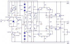
If R42 changes to zener, R43 should be CG, otherwise you have the same error (LTP current variations) like injecting new current into LTP (fixed cascode base).
Proper way in pic. 😉
Proper way in pic. 😉
Attachments
Last edited:
Lazy Cat.
That is littlefishbicycle.com
and it is really a HIFI Power amp
[Dead link removed by moderation for member safety.]
That is littlefishbicycle.com
and it is really a HIFI Power amp
[Dead link removed by moderation for member safety.]
Last edited by a moderator:
closer , just the IPS to go.
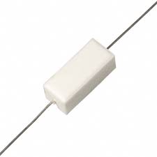
I actually just redesigned the whole thing (below 1) , wanted it to "look" SOTA. Is the choice of resistor OK ? (below 2) 10mm lead- spaced noble emitter resistors - non-inductive ?
Look at the 3 input stages (big attachment 3) , the sphinx , pioneer and luxman get away with the minimum. I am open to a "better" input stage , the input stage has more PCB real estate available than even the CCS/VAS , but let's keep it to some compromise that does not add semi's.
The below OEM's use primitive boosted supplies for the front end. Our PCB will have that as an option , but will default to a rather large 22R/470uf local decoupling scheme to power the input stage. Notice the 4 earth returns (2 for main decoupling , 1 each for vas/ccs and input ground). Notice the jumperless double sided layout that still has the option of jumpers if one want's to "etch their own". I'm sure the finished board will be so "golden" ,that only the "cheapskates" would do that ....😀
- deep into the input stage presently - 😀
OS
Attachments
Last edited:
I like this jfet input stage: http://i.imgur.com/tjBOv.png based on a german made amplifier i have.
Those resistors are exactly what i use in my amplifiers.
Those resistors are exactly what i use in my amplifiers.
I like this jfet input stage: http://i.imgur.com/tjBOv.png based on a german made amplifier i have.
Those resistors are exactly what i use in my amplifiers.
That is like the pioneer. It is real nice , BUT .... more sensitive to compensation (it tends to oscillate) if you don't get it EXACTLY right. Likes to (is more conducive) run a push-pull VAS. The pioneer only used the cascode as it did not have the reduced supply points like your German amp.
I would love to have suggestions on WHAT FET to use ?? , so I could physically
implement it (layout wise). Some are D-S-G vs. a BJT E-C-B , I need to know this to allow for BJT/FET interchangeability.
OS
LSK389B or C from Linear Systems.
dado
Heres another jfet input circuit from another amp i used to have some years ago: http://i.imgur.com/MhM8f.png
Though the 2SK270 is made of unobtanium. The 2SK332 is also obsolete and only found on one single place on the entire net, on ebay sold by syracuse semiconductor/components.
Though the 2SK270 is made of unobtanium. The 2SK332 is also obsolete and only found on one single place on the entire net, on ebay sold by syracuse semiconductor/components.
LSK389B or C from Linear Systems.
dado
I'm on it ... your talking about this "dualie" , correct - http://www.linearsystems.com/datasheets/LSK389.pdf
(below 1)- would be how it would lay out as compared to a BJT (the option). To use the same pads/layout the BJT will be "back to back" ... no biggie (a dab of thermal compound and shrink tubing - AOK) 🙂 . Correct me if i'm wrong , I do not believe this will impact performance. 😕
Input section is the one where you "sweat the details". 😉
OS
Attachments

I actually just redesigned the whole thing (below 1) , wanted it to "look" SOTA. Is the choice of resistor OK ? (below 2) 10mm lead- spaced noble emitter resistors - non-inductive ?
Ok, but... can you leave some space around in order to vertically mount more conventional resistors, if desired?
IMO, this is a really super design and project. One comment. If the performance is as good as I suspect, you'll likely see a difference between output inductors wound on a resistor, vs wound on a plastic form separate from the resistor. The type of resistor and leads probably determine how much effect it has. At least that's what I found in a particular fussy design I once did.
Ok, but... can you leave some space around in order to vertically mount more conventional resistors, if desired?
If that all you had , I see nothing in the "keep out " zones that would not allow for those 5W monsters to be mounted vertically.
By C. Hoffman - IMO, this is a really super design and project. One comment. If the performance is as good as I suspect, you'll likely see a difference between output inductors wound on a resistor, vs wound on a plastic form separate from the resistor. The type of resistor and leads probably determine how much effect it has. At least that's what I found in a particular fussy design I once did.
With BJT's , I know we are at least at the silicon chip level (.0006% THD20), the FET option is slightly less "super" . This can be offset with smaller current mirror degeneration , 10-22R on the Jfet's .... all this to get the loop gain in the same league as the BJT option. All this will be documented. I have only thoroughly tested the simple and cascoded BJT combo's (ss9014/ksc1845 - cascoded and just the ksc1845 as input pair).
The OP output coil is separate from the 4.7R resistor , my screenprint is generic and shows the resistor inside (wrong-resistor is right next to coil). As with any PPM amp , even the OP stage, voltage stage/input, and supply cap traces "star" from a single rail point right at the fuse. Not having an exact center NFB takoff would add hundreds of ppm, as well - wait till you see the input stage/final labeling. 🙂
OS
2SK389 is nearly unobtanium and LSK variation is no better. Although 2SK170 matched pairs can be used, this is also not easily available. A better option would be to use something like the BF862, easily available, SMD and cheap; but very good performance. You ought to either keep its dissipation low or use parallel devices. This way, the amp will be practically realisable for many across many countries.
My reason for post #34 , allowing for E-C-B bipolars or a plug-in 10mm sq. smd fet PCB. This is why most of my amps are "hardware store" variety BJT semi's - sourcing !!!
OS
OS
Very nice OS! I like the concept and it means anyone coming fairly new into amp construction can get a first class result. Looking forward to hearing from all those that are going to build this!
- Home
- Amplifiers
- Solid State
- diyAB Amp - The "Honey Badger"