IMO, since this will probably be wildly popular, I think it should be prototyped by a couple people. There are often stupid little things that can never be caught looking at printouts, that would take it very near perfection. Component hole too small for a desired part, pad not quite right, connection point not optimal, screw head hits a trace, text errors, mechanical spacing errors, I dunno, I've been bit by all of them!
Would this amp be compatible with the 2SC1492/2SA3586?
Thanks
A little lower Vceo (180V) , a little slower (20mhz). But this circuit has quite a wide tolerance , especially the OP stage (ef2). 50-0-50v supply 120w + @ 8 and 250w/4r with those devices.
Conrad , I think this could be 100% , even without a prototype. I already have built 2 dozen. This is the main reason I chose this design for DIYA. But , it could not hurt.
I still would like opinions on the BJT low noise choice. Here is the selection -
Mouser Electronics - Electronic Component Distributor Bipolar Small Signal
(to-92/npn). As I said, most are EBC. Looking for low Cob - NF- 40-65Vceo.
OS
Member
Joined 2009
Paid Member
Now... with traces going down the PCB center , you would either have to jumper the circuit across the rails , or place most of the circuit on either side.
One would be a bad choice and one would waste real estate.
I'm not suggesting you need to change anything, it's getting into details that become a distraction but I would point out that there's nothing wrong in putting the power traces down one side of the pcb and having an asymmetrical layout. When I did this for my TGM amplifier pcb's there were no obvious wasted real-estate and it was all single sided with no jumpers in sight.
I'm not suggesting you need to change anything, it's getting into details that become a distraction but I would point out that there's nothing wrong in putting the power traces down one side of the pcb and having an asymmetrical layout. When I did this for my TGM amplifier pcb's there were no obvious wasted real-estate and it was all single sided with no jumpers in sight.
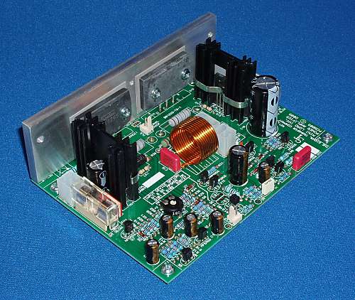
Keep in mind - our 2 top AB manufacturers -
1. Aspen audio -

and 2. Aussie amplifiers (onboard PS)
An externally hosted image should be here but it was not working when we last tested it.
Rails from opposing sides , symmetrical layout. I still appreciate the critique. 🙂
OS
Member
Joined 2009
Paid Member
yeah, but 'everyone' was using symmetrical pcb's before either of these guys came onto the scene so there is a lot of conventional wisdom and experience that sets the stage for others. Not meant as a criticism or to suggest that I know better, but the physics of it says to keep high current wires in pairs - the outbound and the return current next to each other. At higher frequencies than the audio band it's vital and ground plane design becomes a skill. It may not matter as much as taking care of other needs, so perhaps the pcb's you feature above take into account other tradeoffs that favour the layouts chosen. For asymmetrical amplifiers a symmetric pcb is even less relevant. Anyhow, it's getting off-topic, I think your pcb looks darn good.
Last edited:
A little lower Vceo (180V) , a little slower (20mhz). But this circuit has quite a wide tolerance , especially the OP stage (ef2). 50-0-50v supply 120w + @ 8 and 250w/4r with those devices.
Conrad , I think this could be 100% , even without a prototype. I already have built 2 dozen. This is the main reason I chose this design for DIYA. But , it could not hurt.
I still would like opinions on the BJT low noise choice. Here is the selection -
Mouser Electronics - Electronic Component Distributor Bipolar Small Signal
(to-92/npn). As I said, most are EBC. Looking for low Cob - NF- 40-65Vceo.
OS
For Low noise, lowest Cob, high hfe, mpsa18 is excellent. For current mirrors even more so.
For Low noise, lowest Cob, high hfe, mpsa18 is excellent. For current mirrors even more so.
I made a list of compatible BJT's , and the mpsa18 was top gun.
ss9014 is right on it's heels - Cob/noise/gain wise. 🙂
LIST -
NPN input device selection for DIYA-AX
fairchild - cheap/ EBC
2n4401 - GP
ss9014 - LN/HG
mpsa18 - LN/HG
mpsa05 - GP
KSC815 - HG
KSC1008 - GP
KSD1616 - GP
zetex - expensive /EBC
ztx 1051a - LN/HG
ztx 690b - HG
philips - would be pin reversed -CBE (back to back mounting)
BC550 - GP
BC547 - GP
LN = low noise
HG = high gain
GP = general purpose, would work but not really exceptional.
OS
This is a very exciting thread to follow. I've saved a handful of MJ21193/94 along with other TO-247 types and hope to build one or two in the future...
Keep it up!
Keep it up!
This is a very exciting thread to follow. I've saved a handful of MJ21193/94 along with other TO-247 types and hope to build one or two in the future...
Keep it up!
MJ is to-3 (this one needs to-247/to-3p) , 21193/4 is too low Hfe for a EF2. My triple (DBT-luxman) is the beast for the to-3p/to-247 21193/4's.
LIST of outputs ....
For the full 150w
NJW0281/0302
MJL4281/4302
2SA1943/2SC5200
Sanken to-3p's (below 1) quite a selection ... any below would work.
150w (marginally)
Drivers -
MJE15030/31 or 32/33 or 34/35 - optimum ON- semi
2sa1837/2sc4793 - best for 8R use , EF2 would have the most total Hfe .
I've tried most of these devices , so I should document all these choices and include them in the book.
OS
Attachments
To ground plane , or not to ......
I was looking at the famous Doug Self "blameless" -
The Signal Transfer Company: Compact Blameless Power Amplifier
Close inspection of the PCB shows typical rail connections (like this amp) , and a ground plane around the input stage. Self's amp seems to stay PPM despite it's conventional layout (look at the AP THD graph) at 25w. At 100W , who knows ?
I'm at that point with my cad (below 1) , now I just have to decide WHAT ground to connect the plane to. Any pointers ???
OS
Attachments
I'm not a big fan of ground planes on power amps. They just seem like an opportunity to couple signals to where you don't want them. If the purpose of the plane is purely shielding and the reduction of radiated signals, I'd connect it to input signal ground, as that's the one point declared to be "true ground". Either that, or wire it back to the PS ground stub, probably the safest bet.
Member
Joined 2009
Paid Member

I like this one Alex, keeps high currents close together, small signal circuitry away from output inductor. Very nice.
All the pcb's in this thread are lookin' good.
Ground planes aren't simply a grounded equipotential higher frequencies. The 'return' currents through the ground plane will actually follow the trace underneath them that carries the corresponding signal. If you want to control where these currents flow in order to make a star earth you have to think carefully about the design of the ground plane.
Last edited:
A HAH !!
Beautiful , alex. Your work is my inspiration.
First ... only the input filter and input euro-block ground goes after the lifted ground resistor/diodes (5R or 4.7R).
R13,25/ C3,4 go directly to ground (the second "clean one")
You have 2 grounds ... this can work (universally) with another faston placed on the main decoupling ground (hook the 2 grounds together) as this amp (can just) have it's power supply onboard. If a external supply is used (to augment the onboard supply), the 2 separate grounds could go the the main star there.
- no VAS heat-sinking Q10,11,12
- Q13 needs a bigger hole
-C13,17 can only be 10mm LS 25mm unit , limited to maybe 10Kuf X 2.
35mm with 4 pin 22mm would allow apex jr. caps plus 15-22k panasonics. 🙂
-Q1,2 should be E-B-C , most good 45-60V BJT LTP pairs (90+%) are.
- C1 (the input cap) hey! ...what about the wima 5mm or 10mm poly's -
Fix these things and you will have glory.... 😀
Oh BTW - here's mine (below)
Let's have a "shootout" , Alex 😀
OS
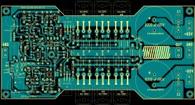
....My contribution, with another arrangement of parts on printed circuit .🙂
Regards Alex .
Beautiful , alex. Your work is my inspiration.
First ... only the input filter and input euro-block ground goes after the lifted ground resistor/diodes (5R or 4.7R).
R13,25/ C3,4 go directly to ground (the second "clean one")
You have 2 grounds ... this can work (universally) with another faston placed on the main decoupling ground (hook the 2 grounds together) as this amp (can just) have it's power supply onboard. If a external supply is used (to augment the onboard supply), the 2 separate grounds could go the the main star there.
- no VAS heat-sinking Q10,11,12
- Q13 needs a bigger hole
-C13,17 can only be 10mm LS 25mm unit , limited to maybe 10Kuf X 2.
35mm with 4 pin 22mm would allow apex jr. caps plus 15-22k panasonics. 🙂
-Q1,2 should be E-B-C , most good 45-60V BJT LTP pairs (90+%) are.
- C1 (the input cap) hey! ...what about the wima 5mm or 10mm poly's -
An externally hosted image should be here but it was not working when we last tested it.
Fix these things and you will have glory.... 😀
Oh BTW - here's mine (below)
Let's have a "shootout" , Alex 😀
OS
Attachments
The grounds between the main caps are too thin for my liking.
I generally keep the main storage caps off the pcb or separately on one side of the pcb a bit like alex did. and have the high current stuff like speaker ground going from the caps and only keep signal ground going between PSU and amp.
I generally keep the main storage caps off the pcb or separately on one side of the pcb a bit like alex did. and have the high current stuff like speaker ground going from the caps and only keep signal ground going between PSU and amp.
The 2STC5949/2STA2121 transistors should be good for the output stage too.
Hey , 5'th
Holy poop!! ... those are the outputs !!!!
http://www.st.com/internet/com/TECHNICAL_RESOURCES/TECHNICAL_LITERATURE/DATASHEET/CD00171942.pdf
woweeee 4A DC soa at 60V. 7.5A /60v 100ms. Those blow the 21193/4's away but with 100+ Hfe.
you would have a growling beast of a 200/350W 8/4 R amp there. That would be conservative, even. 1 pair of these exceed 2 pair of the 5200/1943's easily.
So , a "growling beast" of an amp with (below 1) .... just "fine tuned" both the BJT and FET versions of the cascoded input stage (same" perfect circuit").
quite the FFT , almost audiophile. A slight tradeoff in PPM's for better distortion products.
Simulated with high inductance supplies / resistance to get the ripple a ripplin' , did the "worst case" scenario at 100v p-p/10k ... still nice. 🙂
OS
Attachments
The grounds between the main caps are too thin for my liking.
I generally keep the main storage caps off the pcb or separately on one side of the pcb a bit like alex did. and have the high current stuff like speaker ground going from the caps and only keep signal ground going between PSU and amp.
look below - 7.86A for those traces with just 1 oz. copper. "Imax" (below 1) 12A for 2 OZ @ 20C.
OS
Attachments
- Home
- Amplifiers
- Solid State
- diyAB Amp - The "Honey Badger"