Fuses did not blow. Photos to followDid you have fuses installed and did they blow?
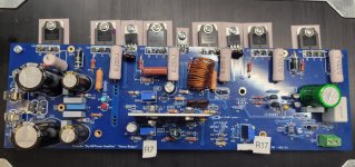
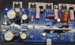
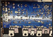
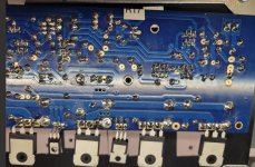
Right channel amp board photos
Attachments
-
 Chip right channel 12.30 1.jpg319.1 KB · Views: 104
 -
 Chip right channel 12.30 2.jpg400.3 KB · Views: 114
 -
 Chip right channel 3.jpg397 KB · Views: 109
 -
 Chip right channel 12.30 4.jpg398.6 KB · Views: 108
 -
 Chip right channel 12.30 5.jpg498.9 KB · Views: 108
 -
 Chip right channel 12.30 6.jpg468.8 KB · Views: 107
You're going to need to measure continuity on all the power and ground rails on the amplifier board and the supply board. Also test the LEDs, R51 and R52. Something must have catastrophically failed to interrupt current on the power rails.
I do notice that the heatsink for the front end is fairly thick. Are you sure none of the transistor legs are shorting out to the heatsink?

1W is fine there. This could be causing the strange behavior of the amp, but it wouldn't stop the LEDs from lighting.
I checked them all for shorts. All good.I do notice that the heatsink for the front end is fairly thick. Are you sure none of the transistor legs are shorting out to the heatsink?
0.5W is Ok, should be 15V but try 27k as R19 first, attached is one of the latest versions of HBOk. I only have a 12V 0.5W diode. Will that work?
I will finish my board exam.
Attachments

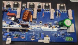
My review of the resistors reveal I have questions about:
R45, R47 and R49.
I can replace them.
Should I also replace the transistors related to them: Q20 & Q16?
R45, R47 and R49.
I can replace them.
Should I also replace the transistors related to them: Q20 & Q16?

Try R19 at 27K before adding the zener? Not quite clear on that.0.5W is Ok, should be 15V but try 27k as R19 first, attached is one of the latest versions of HB
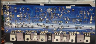
Thanks. I will review them closely.@Chiptech I had a quick look at the your photos, I would be inspecting all of those pads especially the close transistor ones for bridges. It maybe a good idea to remove some solder from those pads to prevent bridging issues and to prevent running into creepage problems.
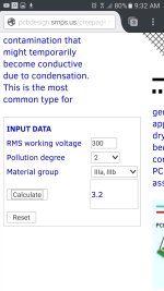
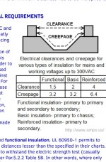
Can you say more about "creepage problems"?
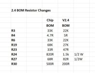
I found them in my stash. Yea.12V is too low, the BOM calls for 15V.
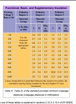
You need a certain amount of gap between the solder pads depending on the difference in voltage otherwise the voltaged can jump the gap. There are creepage tables on online. For example if the difference in voltage between two pads is grater than 64v but less that 81v the gap between the two should be 1.3mm so if you have a massive blob of solder on those pads you will reduce the gap with could allow the voltage to jump the gap, just like a short.Can you say more about "creepage problems"?
Attachments
- Home
- Amplifiers
- Solid State
- diyAB Amp The "Honey Badger" build thread