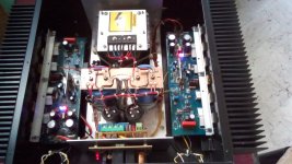
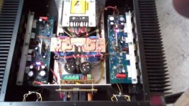
Tony please re read my post. This is standard on many amps.
Stuart I never bridge the grounds of left and right channels.
sorry i got cockeyed....
Hi Stuart please find my simplified CAD drawing attached😀.
I use this arrangement when I build amps. However I use two transformers and two power supplies for dual mono arrangement.
If your amp is quiet now, don't change the wiring. As they say - don't fix what ain't broke.
I am aware that there are different ways of arranging the ground wiring in an amp but I can only go by my experience (which might not be 100% correct).
Bonsai I will re-read your method tomorrow to digest it.
Attachments
PS I forgot to mention that I have not had the need to connect a capacitor on the RCA connector, for my amp builds.
However each DIY amp is slightly different and different solutions are needed.
I'm going to bed....
However each DIY amp is slightly different and different solutions are needed.
I'm going to bed....
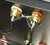
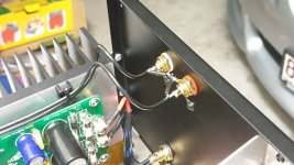
The cap from the bonded shields to the chassis just ensures that at RF the cable screens are effectively shorted to the chassis. Without doing this you can run the risk of RF entering the amplifier housing and radiating inside. With the cap, the cable screen and the source and receive equipment are a single enclosure to RF. Without the cap, this is not necessarily true.
I took a quick look at Harry’s layout - I don’t thing there are huge differences To mine and in some details they may be a bit different. I’ll take a closer look later today.
The two most important things are
1. Keep loops as small as possible
2. Ensure you don’t have common impedance coupling points
Peace
Last edited:
This input ground should not be connected to the chassis.
Ok. I guess that I read this as the input ground should not be connected to the chassis at all.
But from your own schematic I see that what you where saying is that the input ground should not be DC connected to the chassis and using the capacitor as Bonsai recommends to AC connect the signal grounds to the chassis through a capacitor is necessary for the reasons Bonsai gives in his document and his posts above.
Thanks for your input.
I'm not sure if everyone has looked at the 5 ohm resistor (R4) on the schematic that seperates the input ground from the amp ground. This eliminates potential loops within the amp and also from input devices (eg CD player, pre amp) which might have their ground wiring configured in many, many different ways.
Yes the cap that goes from the RCA to chassis stops
RF and other high frequency noise etc. In a very rare case that I saw, about 15 years ago this cap was needed to "stablise" the input in an all FET amp as no other solution could fix the problem.
That is why I recommended it to you Stuart. However none of my amp builds have this issue.
I am not convinced that shorting the two input grounds is necessary. In fact I try and keep both channels completely iscolated from each other. I use two transformers and two power supplies to achieve this and no common wiring except the mains.
I do realise that there are commercial amps that use one power supply and sound great but each person has their own design philosophy and budget. Perhaps I should not mention this as it might start another debate but I seperate the grounds of the positive and negative power supplies and only join them at a star ground point. Why do I do this, because music is asymmetrical and not a symmetrical sine wave. If my method makes your blood boil please note that I also sacrifice chickens before I turn on a new amp😀
Stuart no two amps on this site are built the same, so results differ. Take advice by others and myself as a general recommendations.
If the shorted input grounds on your amp don't present a problem then that's fine!!! If however you want to iscolate the two grounds you need to experiment on YOUR amp and check the results as others can only give you theory.
I will respond to your personal email.
Hi Stuart, it would be interesting to know what happens if you cut the DC short between the channels with everything else the same. Does the noise come back?
Also, doing a cross-talk test with and without this short would be interesting.
Do a full power sine sweep into 8 ohms in one channel, while monitoring the output in the other. Don't use a speaker, use a dummy load... I don't want you to ruin your hearing.
@Harry3: I am interested in the quantifyable improvement. We usually do things like bulding 2 power supplies, seperate the grounds of the positive and negative power supplies and only join them at a star ground point, sacrifice chickens before turning on a new amp, and making deals with cross-road daemons before doing a measurement, BUT, rarely do an A/B comparison to see how much of a difference it made... reduced X-talk by X%, or improved distortion by Y%, etc. I am very interested in that sort of thing... engineer you know.
Best, Sandro
PS I forgot to mention that I have not had the need to connect a capacitor on the RCA connector, for my amp builds.
However each DIY amp is slightly different and different solutions are needed.
I'm going to bed....
Hi Harry, how about a capacitor in parallel with the 5 ohm resistor coupling the signal and the speaker grounds... i.e. in parallel with R4. Do you ever use that?
Thanks!
Hi Sandrohv,
unfortunately I do not have equipment to measure any improvements. That's why I sacrifice chickens and hope for the best LOL😀
On a serious note a cap across R4, which I suggested in post 3926, might indeed give Stuart another solution. I think I would still leave the cap on the RCA connector, to stop the shield from acting like an antenna. It would need to be tested.
I'd like to thank you (and others) for taking the time to assist Stuart.
Unfortunately most of the amps on this site do not include a basic power supply and wiring diagram. It is my guess that most builders do not have an electronics back ground and we all should encourage these people to be successful in this hobby.
Love your video channel.
Best regards
Harry
PS I did not come up with this ground scheme. It was the Legendary Erno Borbely who published it, probably over 30 years ago.
unfortunately I do not have equipment to measure any improvements. That's why I sacrifice chickens and hope for the best LOL😀
On a serious note a cap across R4, which I suggested in post 3926, might indeed give Stuart another solution. I think I would still leave the cap on the RCA connector, to stop the shield from acting like an antenna. It would need to be tested.
I'd like to thank you (and others) for taking the time to assist Stuart.
Unfortunately most of the amps on this site do not include a basic power supply and wiring diagram. It is my guess that most builders do not have an electronics back ground and we all should encourage these people to be successful in this hobby.
Love your video channel.

Best regards
Harry
PS I did not come up with this ground scheme. It was the Legendary Erno Borbely who published it, probably over 30 years ago.
One of the reasons power supply grounding gets confusing is because some builders use a common supply between two channels, while others choose to use a separate supply for each. Each option requires different approaches to connection. Dual supplies are best being treated as two separate amplifiers in one box, keeping everything separate to eliminate the possibility if ground loops. Single shared supplies are actually harder to successfully implement.
Hi Sandrohv,
unfortunately I do not have equipment to measure any improvements. That's why I sacrifice chickens and hope for the best LOL😀
I am hoping that Stuart will do the cross-talk test. That would be great demystifying test.
I'd like to thank you (and others) for taking the time to assist Stuart.
Love your video channel.
Happy to help and thanks! A fun video is coming next.
One of the reasons power supply grounding gets confusing is because some builders use a common supply between two channels, while others choose to use a separate supply for each. Each option requires different approaches to connection. Dual supplies are best being treated as two separate amplifiers in one box, keeping everything separate to eliminate the possibility if ground loops. Single shared supplies are actually harder to successfully implement.
Jwilhelm - Very, very true!
Hi Sando yes I would do a cross talk test on this amp because the input grounds for left and right channels are tied together.
Hi Stuart do you know how to do this test?
Hi Harry, This was I suggested a few posts back:
Feel free to add to the test.
Hi Stuart, it would be interesting to know what happens if you cut the DC short between the channels with everything else the same. Does the noise come back?
Also, doing a cross-talk test with and without this short would be interesting.
Do a full power sine sweep into 8 ohms in one channel, while monitoring the output in the other. Don't use a speaker, use a dummy load... I don't want you to ruin your hearing. Pick a good set of frequencies: 1k, 2k, 5k, 10k, 20k
Feel free to add to the test.
Hi Stuart
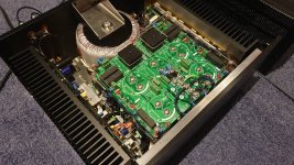
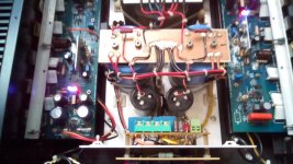
I've looked at your photos and your build is excellent. Congratulations as this is your first amp.
I assume that you're wiring diagram has changed and that the ground wire from the RCA socket goes to the amp pcb. Otherwise you have a loop.
I noticed that your shielded wires, are long. Those caps on the RCA socket that I recommended must stay.
When I get time we will discuss the cross-talk test.
these are the grounding rules i live by:
1. each power supply lead have its own ground return wire to the central ground point..
2. signal wires used as return wires go to central ground point and must never be used to carry current..
3. the speaker ground return wire to zero is never routed thru the pcb grounds the pc board ground goes to the central ground point.
4. the junctions of the main psu filter caps form the ground zero voltage point.
5. this is new, but i have stopped using transformers with center taps, i use a dual bridge configuration...
6. i twist psu cables where practical...
Attachments
Hi Tony,
I basically agree with your comments however I do have a question.
1. Agree
2. Just one question- OS designed the PCB so the ground wire from the RCA goes to the input of the amp board. You elected to take that wire to the star earth point. Did you have issues as this might help Stuart?
3. Agree but with some amps the speaker return goes to the amp PCB without issues.
4. Agree and from there if you want or it's necessary you can go to a ground lift.
5. Agree - two separate windings on a transformer is much preferred.
6. Agree
Edit - did you short the input grounds at the RCA sockets? In my view this would cause a loop.
Last edited:
Hi Tony,
2. Just one question- OS designed the PCB so the ground wire from the RCA goes to the input of the amp board. You elected to take that wire to the star earth point. Did you have issues as this might help Stuart?
in this case the ground signal wire went to the board...
but you can also try removing the resistor for ground on the board and connect the rca to central ground point...
the reason i never connected the speaker return wire to the board is because i felt it violated my first rule...
Thanks for your reply.
Your power supply configuration is similar to Stuarts' and that will help the fault finding. My amp is in pieces in the garage, as I recently moved house and I'm currently finishing some renovations, so I cannot compare.
I noticed that OS ran the speaker return to the power supply as well for most of his amps. He wasn't the best at documentation😀
For some reason the shorted input grounds does not sit well with me.
Considering building this amplifier and I know I saw a list of alternative parts somewhere on this forum but cannot find it now. Given how fast electronic parts become obsolete many parts are obsolete in the diyaudio store BOM. I hope someone knows where to find the alternative active parts list.
- Home
- Amplifiers
- Solid State
- diyAB Amp The "Honey Badger" build thread
