Hi Guy's,
I just had a wiring or component problem / question that I hope someone can help me with.
My Amplifier is finished but I was encountering some hiss in my tweeters for a few seconds after turn on. So I put the amplifier modules back on the test bench so I can try and problem solve with my scope and lab power supply. I'm testing it with 61v rails and bias set to 44mv tp1 to tp2
with approximately 0v DC offset and CCS set to 3.75mA.
The first thing that I noticed was that when I turn on with a 8 ohm dummy load connected and nothing connected to the input I get a lot of high frequency noise approx 400mv peak to peak it ramps up steadily to that and then slowly returns to basically 0mv. It does not seam to have any DC component.
If I short out the input I get the same behavior, but if I touch even the shield of the bridging wire it stops. If I ground the input ground to the speaker ground the high frequency noise is still present.
The real strange part is if I leave it for a few minutes and things warm up or settle the problem goes away just as if I was touching the shielding on the input bridging wire.
Once the problem goes away and I turn off and turn on the power supply the problem is back so I'm not convinced that components warming up has anything to do with it.
I followed the wiring guide by Bonsai and had him check my wiring layout but I'm having this problem and was hoping that someone could help me find a solution or give me some things to check.
.jpg")
.jpg")
.jpg")
.jpg")
I just had a wiring or component problem / question that I hope someone can help me with.
My Amplifier is finished but I was encountering some hiss in my tweeters for a few seconds after turn on. So I put the amplifier modules back on the test bench so I can try and problem solve with my scope and lab power supply. I'm testing it with 61v rails and bias set to 44mv tp1 to tp2
with approximately 0v DC offset and CCS set to 3.75mA.
The first thing that I noticed was that when I turn on with a 8 ohm dummy load connected and nothing connected to the input I get a lot of high frequency noise approx 400mv peak to peak it ramps up steadily to that and then slowly returns to basically 0mv. It does not seam to have any DC component.
If I short out the input I get the same behavior, but if I touch even the shield of the bridging wire it stops. If I ground the input ground to the speaker ground the high frequency noise is still present.
The real strange part is if I leave it for a few minutes and things warm up or settle the problem goes away just as if I was touching the shielding on the input bridging wire.
Once the problem goes away and I turn off and turn on the power supply the problem is back so I'm not convinced that components warming up has anything to do with it.
I followed the wiring guide by Bonsai and had him check my wiring layout but I'm having this problem and was hoping that someone could help me find a solution or give me some things to check.
DIYAB HoneyBadger Amplifer Oscillating
I was having problems with random noises and oscillation at higher powers doing these modifications to the circuit have fixed the problem I think it was because i'm using higher hfe transistors than whats in the original circuit. Maybe this could help with your oscillation.
I was having problems with random noises and oscillation at higher powers doing these modifications to the circuit have fixed the problem I think it was because i'm using higher hfe transistors than whats in the original circuit. Maybe this could help with your oscillation.
Attachments

Last edited:
One quick clarification: "Once the problem goes away and I turn off and turn on the power supply the problem is back so I'm not convinced that components warming up has anything to do with it."
Do you turn off - wait - turn on the power, or do you turn off and immediately turn on the power, when you observe the problem coming back.
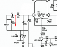
My working theory (which could be wrong) is that it has to do with charging the input cap. Here is an experiment for that. Repeat what you have done, but short as shown in the attached diagram.
Do you turn off - wait - turn on the power, or do you turn off and immediately turn on the power, when you observe the problem coming back.
My working theory (which could be wrong) is that it has to do with charging the input cap. Here is an experiment for that. Repeat what you have done, but short as shown in the attached diagram.
Attachments
One quick clarification: "Once the problem goes away and I turn off and turn on the power supply the problem is back so I'm not convinced that components warming up has anything to do with it."
Do you turn off - wait - turn on the power, or do you turn off and immediately turn on the power, when you observe the problem coming back.
My working theory (which could be wrong) is that it has to do with charging the input cap. Here is an experiment for that. Repeat what you have done, but short as shown in the attached diagram.
Hi Sandro,
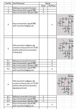
I have preformed some more tests and have put the results into the attached table.
When then noise disappears and I turn off the amplifier, I have been turning it on again with in 5-10 seconds.
Attachments

Can you put a small cap (0.01uF) from input ground to chassis at the RCA socket. You can also try a cap across R4.
Good luck!
Good luck!
I also found these results noted in the attached image.
ST you think having the copper top and bottom on that area of the PCB is creating some kind of capacitor effect?
Maybe, not sure Juan, maybe you can test your pcb, try turning it on with nothing connected to the input and listen to your speakers and see if you notice a difference between something connected and nothing connected.ST you think having the copper top and bottom on that area of the PCB is creating some kind of capacitor effect?
Can you put a small cap (0.01uF) from input ground to chassis at the RCA socket. You can also try a cap across R4.
Good luck!
0.01 uf is big, lots of hf attenuation, i am not sure that this is a good idea..
ST you think having the copper top and bottom on that area of the PCB is creating some kind of capacitor effect?
strays that is hard to measure...
One quick clarification: "Once the problem goes away and I turn off and turn on the power supply the problem is back so I'm not convinced that components warming up has anything to do with it."
Do you turn off - wait - turn on the power, or do you turn off and immediately turn on the power, when you observe the problem coming back.
My working theory (which could be wrong) is that it has to do with charging the input cap. Here is an experiment for that. Repeat what you have done, but short as shown in the attached diagram.
this is the reason that it is never a good idea to leave one side to the coupling cap floating, that is inviting disaster, the 100k in the input discharges the 4.7ufd cap, not that there is a dc charge in there with just ac flowing...
a floating cap tends to accumulate charge, that is why the 100k terminating resistor is in there....
It looks like this fixes the problem.
Question I have my signal grounds bridged. Do I have on or two of these caps. I currently have two. I am thinking that I only need one.
Can you confirm Bonsai?
.jpg")
Question I have my signal grounds bridged. Do I have on or two of these caps. I currently have two. I am thinking that I only need one.
Can you confirm Bonsai?
It looks like this fixes the problem.
Question I have my signal grounds bridged. Do I have on or two of these caps. I currently have two. I am thinking that I only need one.
Can you confirm Bonsai?View attachment 852646View attachment 852647
ok ST I'll check that tomorrow to see if the one I have is behaving the same way
0.01 uf is big, lots of hf attenuation, i am not sure that this is a good idea..
Tony please re read my post. This is standard on many amps.
Stuart I never bridge the grounds of left and right channels.
Stuart I never bridge the grounds of left and right channels.
Hi Harry, I really appreciate your input in this issue.
Are you saying that you never bridge the signal grounds on the RCA connectors as I should in my image?
If you do not. Please provide me some additional details so I can understand why not.
Thank you.
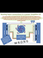
By bridging the both grounds (left and right channels) you MIGHT get an earth loop and or crosstalk etc.
Run seperate wires (or the sheild) from the RCA ground to the input ground. R4 will stop potential earth loops with the power amp ground.
This input ground should not be connected to the chassis.
Hope this makes sense as I'm sending this from my pho
ne and my daughter's 60 kilo dog is dragging me across a park��
Last edited:
Also, speaker GND should go to the speaker GND connection on the amp board, not to the GND on the PSU.
By bridging the both grounds (left and right channels) you MIGHT get an earth loop and or crosstalk etc.
Run seperate wires (or the sheild) from the RCA ground to the input ground. R4 will stop potential earth loops with the power amp ground.
This input ground should not be connected to the chassis.
Hope this makes sense as I'm sending this from my pho
ne and my daughter's 60 kilo dog is dragging me across a park��
Hi Harry, when you have a chance, can you pretty please put a schematic/diagram of your recommendation?
Thanks!!!
It looks like this fixes the problem.
Question I have my signal grounds bridged. Do I have on or two of these caps. I currently have two. I am thinking that I only need one.
Can you confirm Bonsai?View attachment 852646View attachment 852647
Stuart, one cap will do because the grounds are tied together. Typical value 2-5 nF.
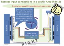
Re the earth loop, remember to run the internal wires to the PCB’s together to reduce the loop area. The reason why you bond the grounds at the input connectors is to trap cross channel loop currents inside the amplifier. If they flow out ( because you have not bonded them) you are likely to cause volt drops across the cabling signal returns That are then in series with the signal.
Attachments
Last edited:
Ok, wow... it seams like we have two different thoughts on whats best.
Either keep the DC short between the signal grounds and use a single 2-5nf capacitor connected to the chassis. Which I know I need to stop this noise.
Or
Follow Harry's advice.
I'll wait to see his schematic.
I do know that based on his advice a capacitor across R4 did remove the noise as well.
Thanks again Harry.
- Home
- Amplifiers
- Solid State
- diyAB Amp The "Honey Badger" build thread