Audio driver transistors 2SC4793 / 2SA1837 are liked but hard to find (digikey US has them). There are also Sanken 2SC4382 / 2SA1668 but I've not used them. MJE15032 / MJE15033 are also good and available. Personally, I find it unlikely that a difference could be detected with human ears. The Honey badger is a very flexible design and will work with many different combinations.
Try Sanken 2SC4883/2SA1859 from Digikey. They are quite fast, and linear.
Sajti
Is anyone here running Honey Badger on +/-70V?
If yes, how does it behave?
I'm asking because in my new 2.1 active system I need to run my main speakers from an amp operating at that voltage and then I'd like to run mid-high drivers using Honey Badger from the same PS. The reason for using different amps is that the main one is not as good as HB at higher frequencies.
Thank you,
cheers,
+\- 70 volts
Just be VERY SURE the rail capacitors are not 63 volt versions!!! All my Honeybadger and Blameless designed amps use 100 volt caps for that extra piece of mind. 🤓
Just be VERY SURE the rail capacitors are not 63 volt versions!!! All my Honeybadger and Blameless designed amps use 100 volt caps for that extra piece of mind. 🤓
Just be VERY SURE the rail capacitors are not 63 volt versions!!! All my Honeybadger and Blameless designed amps use 100 volt caps for that extra piece of mind. 🤓
Yes, of course.
Interestingly, simulation showed that 18V zener performs somewhat better than 15V one with +/-70V rails
cheers,
Weird behavior of one channel!
Hi all!
I'm experiencing some weird things with one of the channels. I've just started to test the amp and one channel is perfect as far as i can see regarding offset and bias. The other one however have some big issues. I followed the build guide very carefully as I'm quite a rookie in electronics.
At start up the faulty channel has a offset of -4 V. This is slowly falling and after 5 min the offset is +-20mv and i can fine tune it with the pot just like the other channel. Bias is stable all the time. Once the channel has stabilized I've tried it with my speakers and it sounds really good. This was fine for a couple of hours of listening and a couple of on/offs (offset -4v at startup still). But now the offset has started to be really unstable and swings up to 60V at some times. (I've disconnected the speakers btw...)
Seems really weird as I did the boards identically with the same parts.
I've measured around a little with my DMM trying to compare the two channels but I cant find anything that is obviously wrong.
Anyone who has experienced something similar or have any ideas?
Thankful for all help!
Regards
Thank you for the tips! Yesterday I checken the solders and did find some gunk around the leds for positive/negative voltage and some other places. Cleaned it up and tested it and the high offset was gone!Hi all!
I'm experiencing some weird things with one of the channels. I've just started to test the amp and one channel is perfect as far as i can see regarding offset and bias. The other one however have some big issues. I followed the build guide very carefully as I'm quite a rookie in electronics.
At start up the faulty channel has a offset of -4 V. This is slowly falling and after 5 min the offset is +-20mv and i can fine tune it with the pot just like the other channel. Bias is stable all the time. Once the channel has stabilized I've tried it with my speakers and it sounds really good. This was fine for a couple of hours of listening and a couple of on/offs (offset -4v at startup still). But now the offset has started to be really unstable and swings up to 60V at some times. (I've disconnected the speakers btw...)
Seems really weird as I did the boards identically with the same parts.
I've measured around a little with my DMM trying to compare the two channels but I cant find anything that is obviously wrong.
Anyone who has experienced something similar or have any ideas?
Thankful for all help!
Regards
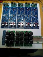
Will do more listening test and stuff but it looks really promising to me��
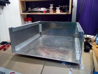
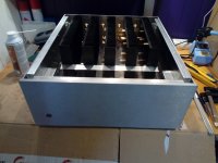
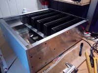
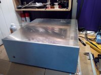
Got some more work done. The heatsinks and front panel finally arrived last week.
This is gonna need some heavy lifting 🙂
Oh yes. Estimated weight is about 32Kg.
What is the size of the chassis? Heatsinks?
the chassis inside is 440mm wide, 500mm deep and 170mm high. heatsinks are 300mm wide, 165mm high. Modushop 4U 300mm sinks. frontpanel is Modushop 4U. 450mm wide and 180mm high.
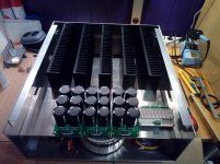
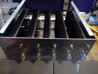
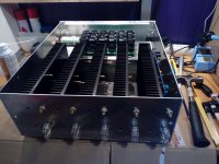
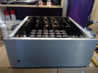
It's slow and steady, but it's getting there 🙂
Still missing 1 red LED and 5 blue LED in the front. and to get som vents on the top and bottom and some paint 🙂
drilled out for IEC on/off switch and fuse holder on the back panel to night.
Still missing 1 red LED and 5 blue LED in the front. and to get som vents on the top and bottom and some paint 🙂
drilled out for IEC on/off switch and fuse holder on the back panel to night.
Attachments
Last edited:
Hello guys!
If someone wants to make this amp and doesnt have the PCBs I can sell mine!
That's reason why I did ask my latest question .
That's reason why I did ask my latest question .
I read somewhere in the post that they sound very very good but I need way more power to drive magnepans! So I need to sell....
- Home
- Amplifiers
- Solid State
- diyAB Amp The "Honey Badger" build thread