Hi Stu,Hi All.
Just been doing a bit more back to basics to help me better understand some of the building blocks of the HB and had the following Question in relation to the input network.
I am assuming that R1,2,3 combined with C1,2 form some form of low pass / high pass filter?
I assume that the coupling capacitor C1 blocks any DC that might be present from the source.
I assume that R3 provides a return path for the input bias current of the amplifier’s input stage. This also keeps the non inverting input node of the amplifier near 0 V.
I assume that the capacitance of C1 against R3 forms a high-pass filter.
I assume that the resistor R2 and capacitor C2 form a first-order input low-pass filter.
I assume that the resistor R1 keeps the input terminal from floating at DC.
If so can someone please provide some more information if this is correct and tell me why active filters are not used?
Barely had a chance to play with mine, too busy dammit.
C1 is DC isolation with R1, eg a hi pass element.
The ratio R2/R3 identical with R5/R6 sets the gain of the amp (same as seen for an op amp in a differential config)
C2 with R3 is a low pass to bypass RF pickup and to reduce the gain for frequencies above the audio band to ensure the gain is less than unity where the phase inverts at the upper end of the bandwidth (to prevent oscillation).
C3/C4 are also DC decoupling, this time for the feedback leg.
Cheers
The input filter is a quick easy way to ensure the HB will not amplify AM (radio) frequencies. The main miller caps at the VAS set unity gain @ 1mhz where there is still 90 degrees of phase margin. Where you hit 180 degrees (oscillator) ,there is attenuation of >-20db ( it would never oscillate). So the input filter just attenuates 100khz - 1mhz , where there still is (purpose-less) usable gain. The input filter has nothing to do with oscillation. PS - should not of said "purpose-less" , extra gain (above native gain) at 20khz + means there is plenty extra for NFB <20khz.
OS
OS
Last edited:
Can the Honey badger be bridged?
MT-200's ,40V rails and 8R , maybe ?
OS
Thanks for those responses. Johno and OS.
Just one last part to my original question.
Is there a reason that an active low / high pass filter is not used?
I assume its because the voltage drop across the input network is not that great considering the input impedance of Q1.
Just one last part to my original question.
Is there a reason that an active low / high pass filter is not used?
I assume its because the voltage drop across the input network is not that great considering the input impedance of Q1.
@Stuartmp
The simple RC roll off is all that is needed. Series C1 is simply to block DC at the input from any previous stage and should be large enough to pass anything above approx 20Hz. Shunt C2 attenuates RF signals in the many MHz range.
Cheers
The simple RC roll off is all that is needed. Series C1 is simply to block DC at the input from any previous stage and should be large enough to pass anything above approx 20Hz. Shunt C2 attenuates RF signals in the many MHz range.
Cheers
Mainly capacitance of filter caps and do in need to put bypass capacitors in the power supply. Also do i need to put bleeder resistors across caps?
Mainly capacitance of filter caps and do in need to put bypass capacitors in the power supply. Also do i need to put bleeder resistors across caps?
Below -
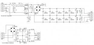
C2 -14 can be much larger 8 X 10kuf/80V . C1 is a RF filter ,
I used 8 X 6800uf/80V on a far larger amp than the HB
C12 + TX is a common mode filter.
BR1 can have snubber caps 250v/.01uf in parallel
with each diode.
R2/3 , I think they should be 3.9K .... I use 5.6k on 60+V supplies.
C6/7 are the small bypass caps you mention.
RT1 is a soft start - negative temp. co-efficient inrush limiter.
12a inrush limiter Inrush Current Limiters | Mouser
OS
Attachments
hi all, I need help with the boards v 2.4, through the fuse I see the same voltage as the rails, what could I have done wrong?
Is there an advantage of going with a higher voltage psu compared to lower voltage? Meaning for maximum power output for the amplifier. Also I understand current plays a part also so say if a unlimited current is available. Also is dual rectifier any advantages over single? This is a mono configuration. Thanks.
Last edited:
hi all, I need help with the boards v 2.4, through the fuse I see the same voltage as the rails, what could I have done wrong?
The fuses provide power from the PSU to the rails. They are "in-line" with power, and open up if there is an overcurrent, etc.
Is there an advantage of going with a higher voltage psu compared to lower voltage? Meaning for maximum power output for the amplifier. Also I understand current plays a part also so say if a unlimited current is available. Also is dual rectifier any advantages over single? This is a mono configuration. Thanks.
Your load (speaker) would determine the PSU requirement. It has been generally recommended to use the build guide suggested transformer for easy to drive speakers, and lower voltage PSU's for harder to drive loads(ex:4R or 6R[R is ohms])
Also, depending on your speakers, there are other things you may need to consider as well.
One important consideration for instance is the output stage options. You need to be sure that the output devices are capable of staying withing their SOA (Safe Operating Area). If you know what your speakers are, There are a lot of knowledgeable people around this forum that can help out with decisions to make it easier.
One important consideration for instance is the output stage options. You need to be sure that the output devices are capable of staying withing their SOA (Safe Operating Area). If you know what your speakers are, There are a lot of knowledgeable people around this forum that can help out with decisions to make it easier.
I'm using 2x45V toroid with dual bridge PS which reduces rail voltages by about 1V but each secondary winding runs only one bridge preventing circulation of direct currents through transformer windings and reduces EMI. Speaker is about 8ohms and all is fine. I tested it with nominal 6 ohm speaker loads and all was fine as well. My HB usees MG6331/9411 power transistors and Toshiba (2sa1930/sc5171) as drivers.
To test SOA capabilities/requirements you can use the attached program.
cheers,
To test SOA capabilities/requirements you can use the attached program.
cheers,
Attachments
The fuses provide power from the PSU to the rails. They are "in-line" with power, and open up if there is an overcurrent, etc.
True, excuse the error, I wanted to say that I see high voltages on R53 and R54 and burns.
the leds do not light up, while if I remove the driver Q15 (MJE15033) everything seems to work, I checked and replaced but the result is the same ...
thank you
Last edited:
I solved, it was not well isolated from the sink.True, excuse the error, I wanted to say that I see high voltages on R53 and R54 and burns.
the leds do not light up, while if I remove the driver Q15 (MJE15033) everything seems to work, I checked and replaced but the result is the same ...
thank you
Finally it works.
I solved, it was not well isolated from the sink.
Finally it works.
Good news!
FYI, R53 and R54 should read rail voltage. If you search on the two Badger threads you will see some discussion on them. Some people are in favor of removing them once the amp is set up, because of the fact that they burn instead of the fuse.
Cheers!
- Home
- Amplifiers
- Solid State
- diyAB Amp The "Honey Badger" build thread