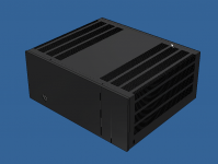
Finally getting somewhere with this build. Its only taken me 3 years. Lol.


Attachments


Last edited:
Nanchangebob I myself have this same problem in only one channel I rebuilt the board and had the same raising bias I was told it could be high frequency oscillation I have switched some transistors and resistors and got better readings but it still takes off. Do not know my post numbers but will scan for them later and let you know. I have been playing the amp on my workbench for months set at a low bias (12mv) and it sound great
Thanks for your replies guys but I think I have the problem figured out.
I received the DCA75 and I really like this neat little test gear, it makes quick work of matching and testing components and it doesn't matter how you connect the leads as it figures it out for you. I found that I had a couple of transistors that were bad and the others measured low hfe. I tested the other 6 outputs I received from mouser and they all measured within 5 percent and did not believe that Digikey sent dead components so I went and did a test with a 317 regulator using the normal pads first and the temperature rose from about 69 degrees F to around 90 degrees F within 10 or 15 minutes. I tried the 3m pads and the temperature of the heat sink stayed at about 70 degrees for the entire 10 to 15 minutes. I don't think the pads are defective only my application of the pads, one side has a thick film that is easily removed and the other side has a thin film which I'm not sure how to remove it without destroying the pad. On the datasheet, it states the thermal conductivity as 3.5 W/m-K with film and 5 W/m-K without. It states in the product description, 3M TCSIP 5549S has permanent PEN film 6 micrometer thick on one side to provide for a non-tacky surface, increased puncture resistance, ease of handling and rework. I'm not sure how to properly use this product and did call 3m for clarification, unfortunately, the woman responsible for it doesn't answer the phone or return calls. For now, I will put it on a shelf and use the old cheap pads.
I have new outputs coming tomorrow after I match them I will install them and I have a good feeling everything will work as it should.
I hope in my tone I didn't imply the design was defective only that I must be making a catastrophic mistake and I was wondering if someone might know what I did wrong. I did suspect it was thermal related and I included the 3m datasheet in my first post as I never used this product before and was wondering if I might have done something wrong.
I just received a call back from the rep at 3M and explained to her how I was using the product and she said that I was doing everything right and it should not respond in the way that it did and that somehow I may have received the wrong material?
They are sending me a new sheet but I will make sure to try it on the LM317 supply before attempting to use it on my amp outputs.
I must be the luckiest guy in the world!
They are sending me a new sheet but I will make sure to try it on the LM317 supply before attempting to use it on my amp outputs.
I must be the luckiest guy in the world!
So you had bad transistors. Now with DCA75 you will be able to test all semis before using them. Looks that replacing these bad ones with good ones should solve the problem. Let us know how your HB performs once you have replaced all the bad components.
cheers,
cheers,
Hi, why in a R36 channel measure 5R on board and 150R out and burn fuses?
The other card reads 150R on board and works properly
The other card reads 150R on board and works properly
Hi Stuartmp, I know what you mean about time. I started my SX-780 rebuild project over a year ago and I am just close to finished now.
Replace old amp with Lichtstark balanced mosfet amplifier ( Had a Badger that was great, but this thing is outstanding )
rebuild power for all tuner chips and upgrade FM output.
Upgrade all Voltage regulators
Rebuild and tune RIAA preamp for MM cartridge.
Add Iphone smoothing amplifier / conditioner.
Add 6922 tube preamp and low noise power supply.
Completely rebuild crossover in Nuance 3CLS tower speakers.
Fix AM chip and busted Balance control.
Now I just have to install it all
Last edited:
MOSFET = super low Rdson ,less than some wire. https://www.onsemi.com/pub/Collateral/NDPL180N10B-D.PDF
Two of them form a solid state relay that can disconnect a speaker at the speed of the protection circuitry.
OS
A great mosfet but as the HB has voltage rails of 60, would that mosfet with a vdss of 100V be sufficient? Wouldnt the mosfets vdss have to be 150V for the HB with 60 volt rails?
Finally
Well, the amp is up and running as it should. I set the bias at 37 mv and after an hour of running my heat sinks are about 30 degrees.
What I found out!
I am blind and an idiot. I put the wrong capacitor in C8, my capacitors measured 4.50pf instead of the 470pf and with my bad eyes, it looked good.😱
As Pete said if you follow the build guide and it will work. I am so relieved and plan to listen to some music tomorrow. I spent most of the day testing it and finishing the case.
I almost forgot to mention, the 3m pads work nicely and they are easy to use, I have a cheap IR thermometer I bought a couple of weeks ago at harbor freight tools and the battery
was low and giving me erroneous readings, installed a new battery and retested heat sink temperature in use and it was fine.
Last edited:
Hi Bob,
Normally I'm very suspicious of new transistor testers, but your report on the DY294 sounds promising.
One thing that is critical no matter what you use to measure transistors is the temperature of the transistor when readings are taken. So do avoid touching transistors, or breathing on them. This goes for sunlight.as well. The best place to match transistors is in a dark location away from air vents.
For small signal transistors, you pretty much have to use a jig that was designed to avoid these problems. It places the pair under test together in thermal contact in a long tailed pair configuration that will allow you to get matches within 1%. You just measure between the collectors for a zero.
Several members have designed boards for these jigs. I think you can find some information in a couple Adcom GFA-565 threads. I designed it years ago in order to get matches after years of having variable results measuring them the way almost everyone does. The basic issue is that you must keep the two transistors at the same temperature if you ever hope them to give you a stable value. I use a CCS for the tail current. It is very effective.
For what it's worth, just trying to help you get what you are intending in the way of matches. I will look into that tester you bought. Sounds really cool.
-Chris
Hi Chris,
I have the DY294 but it died I just bought the Peak Atlas DCA 75 and I really love it, it is much nicer than the DY294 is and I really like the addition of the curve tracer. My DY294 moved around too much and it made matching more difficult.
By the way, I sat and matched my transistors in my basement where it always remains nice and cool. I have read about what you are talking about with temperature so I try to set all the components on a large heat sink to put them at the same temperature. I don't think it is as accurate as what you are suggesting but it's pretty darn good and easy.
Here is a Youtube video that discusses the unit. I really like this thing! YouTube
A great mosfet but as the HB has voltage rails of 60, would that mosfet with a vdss of 100V be sufficient? Wouldnt the mosfets vdss have to be 150V for the HB with 60 volt rails?
I am using IRFP4668 rated at 10mOhm and 200V because my rails are 70V.
Finally getting somewhere with this build. Its only taken me 3 years. Lol.View attachment 742095View attachment 742096View attachment 742097View attachment 742098View attachment 742099View attachment 742100View attachment 742101
Hi stuart
nice enclosure... where did you get it ?
Hi RCruz,
Thanks for your interest.
I designed the case in Autodesk Inventor and had it laser cut from brushed stainless.
The whole amplifier layout was done in Inventor so I knew it would all fit.
Thanks for your interest.
I designed the case in Autodesk Inventor and had it laser cut from brushed stainless.
The whole amplifier layout was done in Inventor so I knew it would all fit.
Thank you... very good work indeed.
I can draw using Solidworks.... I am quite proficient actually but I would like to know where you had it cut.... Maybe I can do something like that also.
I can draw using Solidworks.... I am quite proficient actually but I would like to know where you had it cut.... Maybe I can do something like that also.
I had it cut at a local laser cutting and folding business. Here in Australia its called UniqueLaser. But there are many of them around. The main thing that they need is a flat pattern dxf file and a drawing showing how to bend it.
I am a mechanical engineer and have been designing machines for about 20 years now.
The most important thing to look for with a laser cutting and folding business is that they have a CNC break press. This automatically loads your sheet of laser cut sheet and moves it to the precise position before folding. You will also need to ask them what the K factor is for the material that you are using so the material used up in the folds is calculated correctly.
I will attach my drawing of the base as a sample for you.View attachment _Amp Base.pdf
Hi Bob,
Thanks for that. I'm always interested in what might be a good piece of equipment for transistor measurements. Curve tracers generally take too long for service situations.
I can't see how you could make better measurements than you are now considering the lack of a jig. You should try to whip one together. I built my first on on a piece of perf board. I was frustrated with a crappy match and needed something, like NOW. So it went from idea to something useful in less than an hour. Later I added the PNP section, then committed it to copper when the first one began to fall apart. I used it that much.
Here is my PCB artwork. It's 1/10" spacing and you can use the toner transfer method with it. The schematic is somewhere, but it is stone simple.
-Chris
Attachments
This it's the precision transistor matcher that I designed and made.
Initially it just did PNP transistors but with a little home made tweak it now does PNP and NPN.
It also has a fan to keep air flowing so the transistor are tested at the same temperature.


Initially it just did PNP transistors but with a little home made tweak it now does PNP and NPN.
It also has a fan to keep air flowing so the transistor are tested at the same temperature.
- Home
- Amplifiers
- Solid State
- diyAB Amp The "Honey Badger" build thread