Hi Andrew... So are you saying that if I connect this coil more directly to the circuit with shorter leads the inductance will change?
Yes 5.7 Turns is about right.
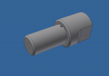
The coil shown is 14mm ID with a wire Diameter of 1.3mm
Sent from my SM-G920I using Tapatalk
Yes 5.7 Turns is about right.
The coil shown is 14mm ID with a wire Diameter of 1.3mm
Sent from my SM-G920I using Tapatalk
https://www.eeweb.com/toolbox/coil-inductance
Try this to calculate the inductabce . yes, aa battery 8 turns is right on the money.
Try this to calculate the inductabce . yes, aa battery 8 turns is right on the money.
Ok. I'll try 8 turns on a AA battery and post my findings.
Sent from my SM-G920I using Tapatalk
Sent from my SM-G920I using Tapatalk
And use a close coupled wire pair to connect the inductor to the measurement circuit.Ok. I'll try 8 turns on a AA battery and post my findings.
Sent from my SM-G920I using Tapatalk
Or just rely on the prediction from a recommened calculator.


Ok that's the coil made.
10 turns to start with and I cut it back once I get it on the scope.
Sent from my SM-G920I using Tapatalk


Ok based on that. Short leads are the go. Thanks Andrew.
Only thing is from the numbers I need 15 turns or so.
I will try again tomorrow with 17 turns and work my way down again.
Sent from my SM-G920I using Tapatalk
15T seems too many based on the 14.5mm bobbin diameter and the inductor calculators I have used.
15T seems too many based on the 14.5mm bobbin diameter and the inductor calculators I have used.
You are right. But I don't want to have to spend time winding another if its to short again.
Do you guys have any recommendations for a good input coupling cap (C1)?
I currently have a Wima MKP 4.7uF in there, but would be interested to see what a non-metalized cap could do.
I currently have a Wima MKP 4.7uF in there, but would be interested to see what a non-metalized cap could do.
A close coupled air cored inductor wound on the same bobbin with the same wire will roughly quadruple it's inductance when you double the number of turns.
i.e. if 7T ~0.6uH, then 10T ~1.2uH and 14T ~2.4uH
i.e. if 7T ~0.6uH, then 10T ~1.2uH and 14T ~2.4uH
Hey guys! Just checking in!
After succesfully building the Mains Bulb tester, and after disassembling the amp, I have found the problem for the fuse blowing!
I should add, this mains bulb testing is really great, since I could "see" in which module the problem might be.
The V- fuses blew simply because of the poor speaker connector insertion in the test speakers. They were connecting to each other, thus the shorting problem.
Using the MBT, I have found that my 1000VA toroidal became dead silent. Before, it was making some buzzing noise... Can you help me how to get rid of that I dont want to have the MBT always connected, but want to get rid of that buzz..
I attached a sound clip of the transformer buzz without MBT.
Sound Clip: Transformer Buzz without MBT
Also, I was trying several connections to reduce the noise problem which was happenning with me. Don't know why, but I found out that if I connect the signal ground with the speaker ground, my speakers stop emitting the strange noise which was initially my problem. Good, but can someone tell me why?
I attached a sound clip of the signal gnd connecting to speaker gnd before after comparison
Sound clip: Speaker gnd to signal gnd before/after
Thanks for the help guys!


Ok So I made the coil and I have the correct frequency.
I have measured the capacitance accurately too using my scope.
Now the question is. Why do I more turns then people are saying.
Maybe you can help me out AndrewT

Sent from my SM-G920I using Tapatalk
Ok. I found the problem. That web site is not calculating the impedance correctly for some reason. Or the formula is not for these types of coils / inductors.
I used 2 other sources and got answers that match my oscilloscope results.
I also manually caculated it using there supplied forumlas.
I current have 1.692uH
So from my findings I still need to make the coil a little shorter. But at least I can do a sanity check with a formula that works.
I hope this help someone else.
I will keep working on this until I get the correct result.
Cheers.


Sent from my SM-G920I using Tapatalk
I used 2 other sources and got answers that match my oscilloscope results.
I also manually caculated it using there supplied forumlas.
I current have 1.692uH
So from my findings I still need to make the coil a little shorter. But at least I can do a sanity check with a formula that works.
I hope this help someone else.
I will keep working on this until I get the correct result.
Cheers.
Sent from my SM-G920I using Tapatalk
Hey guys! Just checking in!
...
Thanks for the help guys!
I'm Still waiting for someone to help! <3
Done... 1.5037uH
Here are the results if anyone is interested.


Sent from my SM-G920I using Tapatalk
Here are the results if anyone is interested.
Sent from my SM-G920I using Tapatalk
And that's it my boards are complete.
Just need to install the transistors and stand offs on the heatsinks.


Sent from my SM-G920I using Tapatalk
Just need to install the transistors and stand offs on the heatsinks.
Sent from my SM-G920I using Tapatalk
- Home
- Amplifiers
- Solid State
- diyAB Amp The "Honey Badger" build thread