Sounds promising, so far. The price of this protection board I can see at your homepage, I assume?
Best regards!
There are multiple boards required to put a complete system together and multiple options of each to custom tailor the system to the amplifier and builders preferences. Most people email us their build info and we suggest parts to suit.
These systems are designed so key parts are mounted in sensible locations, eliminating extra noisy/ugly wiring. Speaker relays mount on output binding posts. Control transformer, power relays, softstart, fusing ect all on a single board so power in, transformer feed(s) out without a bunch of extra wire. Make for a much neater and easier build.
Mmmmhhwmpf, well, that would work. But too much hassle for a bunch of crappy eBay boards, and I'm sure it wouldn't look very pretty 🙂
Say, do you really have a PMMA (PerspexTM) or PC lid on top of your case (not to be taken very seriously...)?
Best regards!
I may have the schematic somewhere in my workshop, will have to dig it out. In the meantime, here's a link to the units I used (rather basic easy-peasy stuff). I converted these stereo units to single channel (paralleled the two sides of the relay), and used one of those units for each channel.
The ability to use an isolation circuit for the grounds depends on how the DC detection circuit operates. Most are very high impedance circuits looking for DC voltage to be present, so a 10 ohm resistance in series really has no bearing on this. Unfortunately with a uPC1237 there are other parts of the system relying on this same connection to ground, so it's unlikely it will work reliably with this resistor added.
Kay Pirinha's suggestion of dual control supplies is likely the best option with these boards. There are lots of small DC supply or DC to DC converters that can be used for this. I've got some tube heater supplies designed that can be altered to any voltage output, and have dual isolated outputs that would work perfectly here.
Attachments
The ability to use an isolation circuit for the grounds depends on how the DC detection circuit operates. Most are very high impedance circuits looking for DC voltage to be present, so a 10 ohm resistance in series really has no bearing on this. Unfortunately with a uPC1237 there are other parts of the system relying on this same connection to ground, so it's unlikely it will work reliably with this resistor added.
I am not planning to insert resistors in the connections to the audio GNDs, because would most likely upset the DC sensing. My idea was to insert the resistors between the DC protection units and their (combined) PSU. Depending on the current drawn by the protection units, this would result in some voltage loss across the resistors, but it would float the units against each other, and break the direct connection of the audio GNDs via the DC*protection PSU.
Kay Pirinha's suggestion of dual control supplies is likely the best option with these boards. There are lots of small DC supply or DC to DC converters that can be used for this. I've got some tube heater supplies designed that can be altered to any voltage output, and have dual isolated outputs that would work perfectly here.
Using separate voltage supplies is certainly the cleanest way to go. But that would mean adding two more boards with two more transformers to the chassis. Not very elegant... I'd prefer the much cleaner 21st century solution, which would act as a replacement for the inrush limiter and the DC protection.
Actually the resistors to ground for the DC detection aren't an issue. There's usually a 47k or 100k resistance in series with the circuit before the AC filter. 47000 or 47010 ohms really is no different to it. I'm not sure how the 10R resistor would work in the supply though. That depends on the circuit. It's tough to figure out an easy fix without seeing a schematic.
Dual control transformers wouldn't be necessary for your circuit. The picture I posted was a supply with a dual secondary transformer with two isolated output regulator circuits, so it gives you two completely separate control supply outputs from a single transformer. The 21st century solution is much neater though. High power mosfet relays are much safer for your speakers too.
Dual control transformers wouldn't be necessary for your circuit. The picture I posted was a supply with a dual secondary transformer with two isolated output regulator circuits, so it gives you two completely separate control supply outputs from a single transformer. The 21st century solution is much neater though. High power mosfet relays are much safer for your speakers too.
Using separate voltage supplies is certainly the cleanest way to go. But that would mean adding two more boards with two more transformers to the chassis. Not very elegant... I'd prefer the much cleaner 21st century solution, which would act as a replacement for the inrush limiter and the DC protection.
I'm not thinking of transformers. What about these, or even much cheaper?
Best regards!
Say, do you really have a PMMA (PerspexTM) or PC lid on top of your case (not to be taken very seriously...)?
No, I prefer fused quartz, doesen't melt so easily. Or I might install a webcam inside the chassis! Well, aehm, actually, that will require yet another PSU... 🙂
Actually the resistors to ground for the DC detection aren't an issue. There's usually a 47k or 100k resistance in series with the circuit before the AC filter. 47000 or 47010 ohms really is no different to it. I'm not sure how the 10R resistor would work in the supply though. That depends on the circuit. It's tough to figure out an easy fix without seeing a schematic.
I couldn't find the schematic in my workshop chaos, so I just tried my resistors idea. I used two 10Ω resistors in the PSU-0V connections of the DC protection units to make their grounds float from each other. The resistors only reduce the voltage at the protection units by about 0.6 V (and less before the relays are activated), and the units seem to happy with this. Everything works okay.
While I had the lid off the Honey Badger, I also cut the leads of the LC caps just to see what the effect on the the sound of the amp is. I can confirm that the Honey Badger sounds (much!) better without the LC caps.
Coming back to my bias issue (#2476). I changed the bias spreader circuit by adding a voltage source of roughly 0.38V. Now, bias is quite stable.

Do you see any drawbacks of introducing the extra circuit? Well LTSpice tells me I(R56) is 1.8mA reducing I(CE) of Q13. Does this makes any difference? I have no clue why the CCS has been set to ~7mA. Should I now increase it to 9mA?

Sorry for bringing this up again. But I hope someone can give me hint if the extra circuit could introduce any trouble (e.g. because the current through the original part of the bias spreader is reduced by ~2mA).
Hi Zymorg,
Cannot remember if its this thread or the honey badger thread where OS recommended increasing the CCS current to 10mA (R27 down to 62 or 56) to further reduce noise and distortion.
Regards
John
Cannot remember if its this thread or the honey badger thread where OS recommended increasing the CCS current to 10mA (R27 down to 62 or 56) to further reduce noise and distortion.
Regards
John
Hi Zymorg,
Cannot remember if its this thread or the honey badger thread where OS recommended increasing the CCS current to 10mA (R27 down to 62 or 56) to further reduce noise and distortion.
This was with the mje340/350 .
Cannot remember if its this thread or the honey badger thread where OS recommended increasing the CCS current to 10mA (R27 down to 62 or 56) to further reduce noise and distortion.
This was with the mje340/350 .
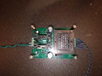
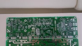
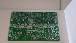
Hi All. I have some extra Honey badger PCB boards that I had made so if anyone wants a pair and lives in Australia send me a PM and I'm sure that we can arrange something.
Attachments

Hi All. I have some extra Honey badger PCB boards that I had made so if anyone wants a pair and lives in Australia send me a PM and I'm sure that we can arrange something.
These boards look nice, but I believe they are a little different from my V2.4 boards I bought from the diyAudio store. Your boards are labelled "version 1.6", but I am not sure how this relates to the the Honey Badger version(s). Can you describe how they are different (or not) from the V2.4 boards that were available from the diyAudio store?
These boards look nice, but I believe they are a little different from my V2.4 boards I bought from the diyAudio store. Your boards are labelled "version 1.6", but I am not sure how this relates to the the Honey Badger version(s). Can you describe how they are different (or not) from the V2.4 boards that were available from the diyAudio store?
I believe that the boards are a clone of the 2.4 board. They also have an RCA output directly on the board and some extra solder reinforced tracks in some important locations. Here is a video I found with some other information. https://youtu.be/M5zlFYZ9Bc8
question the diode for the "Baker clamp diode" is part number is that MMSD4148 ? a 1N4148 can be use there ? also what does the baker clamp do on the amplifier performance ?
question the diode for the "Baker clamp diode" is part number is that MMSD4148 ? a 1N4148 can be use there ? also what does the baker clamp do on the amplifier performance ?
Hi Juan,
here is what i found http://www.diyaudio.com/forums/soli...ents-through-hole-transistors.html#post453754
and If memory serves right, I believe Terry was the first person to experience what the missing diode has an effect at clipping. its here somewhere..... cant seem to find it.
reg
Prasi
Last edited:
question the diode for the "Baker clamp diode" is part number is that MMSD4148 ? a 1N4148 can be use there ? also what does the baker clamp do on the amplifier performance ?
BAV21 diode. Mentioned in post 807 here: http://www.diyaudio.com/forums/soli...honey-badger-build-thread-81.html#post3755517 .
- Home
- Amplifiers
- Solid State
- diyAB Amp The "Honey Badger" build thread