Every current MUST return to the Source, not to a common point.
The god of amplifiers has spoken. Star grounding is wrong.
Carry on with your thoughts and continue to separate the wire pairs.
Did you see me give this advice anywhere? In the diagram I drew it obviously showed wire pairs running together.
Carry on nit picking and trying to show your superior intellect. Maybe some day you can actually do some of these things you claim to be an expert on.
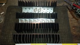
While staying on a visit at my father's yesterday, I dug out a small box containing two pairs of heat sinks that I bought as a high school pupil from a surplus vendor at the end of the 1970ies. Each HS measures 277 x 93 x 45 (WxHxD) mm and has 19 fins.
Yes, there are some holes, but, hey, it's surplus and they were cheap, as far as I recall.
One pair I've populated then with five pairs of 2N3442's for a pair of RCA style amplifiers that I've planned - but that never were done yet. Perhaps their time will come...
Can the thermal resistance of these heatsinks measured or, at least, estimated? And are they suitable to build a pair of Honey Badgers, fed from ±48 Vdc?
Best regards!
Attachments
Last edited:
Coming back to my bias issue (#2476). I changed the bias spreader circuit by adding a voltage source of roughly 0.38V. Now, bias is quite stable.

Do you see any drawbacks of introducing the extra circuit? Well LTSpice tells me I(R56) is 1.8mA reducing I(CE) of Q13. Does this makes any difference? I have no clue why the CCS has been set to ~7mA. Should I now increase it to 9mA?

Do you see any drawbacks of introducing the extra circuit? Well LTSpice tells me I(R56) is 1.8mA reducing I(CE) of Q13. Does this makes any difference? I have no clue why the CCS has been set to ~7mA. Should I now increase it to 9mA?
While staying on a visit at my father's yesterday, I dug out a small box containing two pairs of heat sinks that I bought as a high school pupil from a surplus vendor at the end of the 1970ies. Each HS measures 277 x 93 x 45 (WxHxD) mm and has 19 fins.
Yes, there are some holes, but, hey, it's surplus and they were cheap, as far as I recall.
One pair I've populated then with five pairs of 2N3442's for a pair of RCA style amplifiers that I've planned - but that never were done yet. Perhaps their time will come...
Can the thermal resistance of these heatsinks measured or, at least, estimated? And are they suitable to build a pair of Honey Badgers, fed from ±48 Vdc?
Best regards!
I would be surprised if you wouldn't be fine with these heatsinks. I biased the output stages of my Honey Badgers quite a bite "hotter" than the standard described in the build guide, and the heatsinks are hardly warm.
Question answered, partially at least:
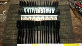
I applied 110 W of dissipation power per eight of those 2N3442 devices (14 Vdc, 7.9A), using the ninth one to drive them in Darlington mode (the tenth I left unused), and observed a temperature rise of 60 centigrades (from 15 deg to 75 deg). This calculates to about .55 centigrades per watt. I didn't measure the driver's emitter current, so the value might even be somewhat lower per the dissipation of that. Does this sound sufficient?
Best regards!
Hi Kay, nice heat sinks in pristine condition, should be good to go with badger. have you had a dig at the OS's 1972 RCA amp that i made a layout for?While staying on a visit at my father's yesterday, I dug out a small box containing two pairs of heat sinks that I bought as a high school pupil from a surplus vendor at the end of the 1970ies. Each HS measures 277 x 93 x 45 (WxHxD) mm and has 19 fins.
Yes, there are some holes, but, hey, it's surplus and they were cheap, as far as I recall.
One pair I've populated then with five pairs of 2N3442's for a pair of RCA style amplifiers that I've planned - but that never were done yet. Perhaps their time will come...
Can the thermal resistance of these heatsinks measured or, at least, estimated? And are they suitable to build a pair of Honey Badgers, fed from ±48 Vdc?
Best regards!
reg
Prasi
Last edited:
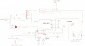
hi Jeff,Here's a diagram for a monoblock wiring example. This is for with out 21'st century protection, but yours should be similar. Ignore the crossover.
here is somewhat of an extension of your excellent amp wiring example that you had shared with me.
one can remove the things that are not there in their builds.
reg
Prasi
PS I do not know if the sch is clear, one would require quite a bit of study to decipher this schematic.
Attachments
Hi Kay, nice heat sinks in pristine condition, should be good to go with badger. have you had a dig at the OS's 1972 RCA amp that i made a layout for?
Thanks, Prasi! No, I didn't yet. Would you please give me a hint?
Unfortunately I saw the 2N3442's literally tiny fT of some super lowish 80 kHz. So I'll have to force them to work at low hFe, i.e. driving them with high base currents. But, when I got them, I was just impressed by their ratings and didn't even know from this parameter called fT. And - they didn't cost me anything, as the company I've been working for in my holidays gave them to me for free.
Best regards!
hi Kay,Thanks, Prasi! No, I didn't yet. Would you please give me a hint?
Unfortunately I saw the 2N3442's literally tiny fT of some super lowish 80 kHz. So I'll have to force them to work at low hFe, i.e. driving them with high base currents. But, when I got them, I was just impressed by their ratings and didn't even know from this parameter called fT. And - they didn't cost me anything, as the company I've been working for in my holidays gave them to me for free.
Best regards!
here is the link i was referring to regarding ostripper's rca amp modded. http://www.diyaudio.com/forums/solid-state/145306-rca-1972-basic-amplifier-mods-14.html#post4845028
reg
Prasi
Can the thermal resistance of these heatsinks measured or, at least, estimated?
of course......ESP - Heatsink design and transistor mounting
And are they suitable to build a pair of Honey Badgers, fed from ±48 Vdc?
IMO, yes......
hi Jeff,
here is somewhat of an extension of your excellent amp wiring example that you had shared with me.
one can remove the things that are not there in their builds.
reg
Prasi
PS I do not know if the sch is clear, one would require quite a bit of study to decipher this schematic.
Hi Prasi,
what's that Protection Board you're showing in your wiring schematic?
@AJT: Thanks, measurement is already done: The thermal resistance of my heat sinks measures about .55K/W.
Best regards!
since i use 2mm aluminum chassis, i see to it that
the chassis served as extension heatsink, to utilize the extra surface area....
that is done by mounting the heatsinks like so....
ant powder coating it matt black helps too....
the chassis served as extension heatsink, to utilize the extra surface area....
that is done by mounting the heatsinks like so....
ant powder coating it matt black helps too....
Hi Prasi,
what's that Protection Board you're showing in your wiring schematic?
Best regards!
Hi Kay,
it is the 21st century protection board by Vzaichenko and JWilhelm. http://www.diyaudio.com/forums/soli...1st-century-protection-board.html#post4110406 . just as an example.
regards
Prasi
That layout & wiring diagram looks very good.hi Jeff,
here is somewhat of an extension of your excellent amp wiring example that you had shared with me.
one can remove the things that are not there in their builds.
reg
Prasi
PS I do not know if the sch is clear, one would require quite a bit of study to decipher this schematic.
You have managed to keep all the Flow and Return pairs close coupled.
Even the speaker Return follows the Flow route from the amplifier and then follows the power routes from the PSU.
Well done.
The only exception is the single wire MAG to Chassis via the Disconnecting Network. This should only pass interference to the enclosure in normal operation.
I see no separated star ground and no need for one.
All the voltage references appear to be on the PCBs and thus no need for external voltage reference wiring.
Last edited:
Does this diagram differ from the one I posted or are you jusr reaffirming you are truly lost?That layout & wiring diagram looks very good.
You have managed to keep all the Flow and Return pairs close coupled.
Even the speaker Return follows the Flow route from the amplifier and then follows the power routes from the PSU.
Well done.
The only exception is the single wire MAG to Chassis via the Disconnecting Network. This should only pass interference to the enclosure in normal operation.
I see no separated star ground and no need for one.
All the voltage references appear to be on the PCBs and thus no need for external voltage reference wiring.
Here is a full list of our posts.
You asserted that
"Everything should return to a common point,"
and I replied with
"Jw said
There seems to be misunderstanding on what "return to source" means compared to "return to a common point".
To me they are different. The first refers to a (unique) source, with each source being a different return point for all the different current routes and their associated sources.
Common point implies that all sources must originate at some common source. this is not the case in most amplifiers. there are a multiplicity of Sources in an amplifier.
I assert that all current from a source MUST return to that source.
I read return to a common point as being different.
Can you explain why or where they could be the same?
You asserted that
"Everything should return to a common point,"
and I replied with
"Jw said
My suggestion is to ignore this completely. Every current MUST return to the Source, not to a common point."Everything should return to a common point,
There seems to be misunderstanding on what "return to source" means compared to "return to a common point".
To me they are different. The first refers to a (unique) source, with each source being a different return point for all the different current routes and their associated sources.
Common point implies that all sources must originate at some common source. this is not the case in most amplifiers. there are a multiplicity of Sources in an amplifier.
I assert that all current from a source MUST return to that source.
I read return to a common point as being different.
Can you explain why or where they could be the same?
Chassis ground isn't a good place to join returns all together. Everything should return to a common point, usually on the supply ground. Often you find the chassis/earth ground from the supply needs to be done through a loop breaker to eliminate hum.
I am looking again at your "simplified" wiring diagram
The antek0124 is a dual primary transformer.
You have shown two reds together and two blacks together.
Think of driving one primary winding. Where are your Flow and Return PAIR?
Twist them as a close coupled pair all the way from entering the enclosure/chassis until they reach the insulation of the transformer.
Repeat for the second primary.
I think you will end up with one red and one black twisted as a PAIR. And another red and black twisted as a pair.
DO this for EVERY inter-module connection.
eg,
is that a soft start for the big transformer? Then it should have mains power PAIR arriving from the mains input to the soft start. You do not split the pair into separate wires and run those mains wires to different destinations. Your MUST keep them as a close coupled pair all the way from Source to Receiver.
Jw saidMy suggestion is to ignore this completely. Every current MUST return to the Source, not to a common point.
Keep the loop area of every inter-module connection at a minimum.
This is easily achieved by thinking of EVERY connection as a close coupled PAIR. Twisting or coaxial is the best way to do this. Many connections will not suit coaxial, so that leaves twisted pair as your solution. That implementation is exactly opposite to Jw's advice.
Star grounding techniques are now wrong? Thank you for again basically regurgitating what I just said, but saying I'm wrong.
In his imaginary amplifier builds power must not come from a power supply. It would be a lot easier accepting advice and constant correction if he'd ever actually done what he's such an expert on.
The god of amplifiers has spoken. Star grounding is wrong.
Carry on with your thoughts and continue to separate the wire pairs.
Did you see me give this advice anywhere? In the diagram I drew it obviously showed wire pairs running together.
Carry on nit picking and trying to show your superior intellect. Maybe some day you can actually do some of these things you claim to be an expert on.
That layout & wiring diagram looks very good.
You have managed to keep all the Flow and Return pairs close coupled.
Even the speaker Return follows the Flow route from the amplifier and then follows the power routes from the PSU.
Well done.
The only exception is the single wire MAG to Chassis via the Disconnecting Network. This should only pass interference to the enclosure in normal operation.
I see no separated star ground and no need for one.
All the voltage references appear to be on the PCBs and thus no need for external voltage reference wiring.
Does this diagram differ from the one I posted or are you jusr reaffirming you are truly lost?
Last edited:
- Home
- Amplifiers
- Solid State
- diyAB Amp The "Honey Badger" build thread