Yep, I agree, that's why this is a flagship design of DIYA, i respect OS. HB is a stubborn animal, one should have a look at Gods Must Be Crazy II.
But I would like to understand why some in some designs , the VBE should track o/p device and why in some designs, it should track drivers (P3A)
But I would like to understand why some in some designs , the VBE should track o/p device and why in some designs, it should track drivers (P3A)
Last edited:
what transformer is best to use for dual mono setup with the honey badger?
It depends.
What exactly do you mean by "dual mono"? Two mono block amplifiers, each with its own transformer? Or a stereo amp with one single transformer, but otherwise separate power supplies for each channel?
Also, what rail voltage are you aiming for? The Honey Badger will work well with a range of voltages (mine has +/- 45 VDC, but most use higher voltage).
with the "dual mono" only the chassis is common to both channels,
some even went as far as having two IEC inlets...
some even went as far as having two IEC inlets...
Need help with wiring
I think I bit off more than I can chew with the Honey Badger. I've had it nearly done for a while but I'm not sure of the final wiring. Attached is a wiring diagram that probably looks confusing but it's my best attempt at figuring out how to do this. I would really appreciate some help in reviewing this to see if I'm on the right track.
I think I bit off more than I can chew with the Honey Badger. I've had it nearly done for a while but I'm not sure of the final wiring. Attached is a wiring diagram that probably looks confusing but it's my best attempt at figuring out how to do this. I would really appreciate some help in reviewing this to see if I'm on the right track.
Attachments
Matt
draw just one channel, so that you can see what you are doing.
Build this one channel and prove to yourself that you have no mistakes.
Make sure the Mains Bulb Tester stays off at each stage of the assembly.
Measure the output offset and output hum + noise.
Once that is proved, then copy it for the second channel.
The first mistake I can see (and I went no further) is at the unput. You have two wires from the input going off to different destinations. Why?
Matt
draw just one channel, so that you can see what you are doing.
Build this one channel and prove to yourself that you have no mistakes.
Make sure the Mains Bulb Tester stays off at each stage of the assembly.
Measure the output offset and output hum + noise.
Once that is proved, then copy it for the second channel.
The first mistake I can see (and I went no further) is at the unput. You have two wires from the input going off to different destinations. Why?
Thanks! To get even simpler, here is just the power wiring for one channel. This should be much easier to read.
Attachments
Chassis ground isn't a good place to join returns all together. Everything should return to a common point, usually on the supply ground. Often you find the chassis/earth ground from the supply needs to be done through a loop breaker to eliminate hum.
Chassis ground isn't a good place to join returns all together. Everything should return to a common point, usually on the supply ground. Often you find the chassis/earth ground from the supply needs to be done through a loop breaker to eliminate hum.
Can you recommend a circuit? All the info I'm finding is for car audio.
Rod Elliot: http://sound.whsites.net/earthing.htmCan you recommend a circuit? All the info I'm finding is for car audio.
Thanks! To get even simpler, here is just the power wiring for one channel. This should be much easier to read.
I used the GND / 0-Volt connectors on the Badger PCB to connect the Badger PCBs to PSU-GND and speaker return. And I did not connect the RCA inputs to the chassis. And I used ground loop breakers to connect the PSU-GNDs to chassis.
I thought you would be able to wire up one channel simply.Thanks! To get even simpler, here is just the power wiring for one channel. This should be much easier to read.
But your new simplified diagram has got me stumped.
Here's a diagram for a monoblock wiring example. This is for with out 21'st century protection, but yours should be similar. Ignore the crossover.
Thanks but honestly that schematic is over my head. I don't know what I'm looking at.
I am looking again at your "simplified" wiring diagram
The antek0124 is a dual primary transformer.
You have shown two reds together and two blacks together.
Think of driving one primary winding. Where are your Flow and Return PAIR?
Twist them as a close coupled pair all the way from entering the enclosure/chassis until they reach the insulation of the transformer.
Repeat for the second primary.
I think you will end up with one red and one black twisted as a PAIR. And another red and black twisted as a pair.
DO this for EVERY inter-module connection.
eg,
is that a soft start for the big transformer? Then it should have mains power PAIR arriving from the mains input to the soft start. You do not split the pair into separate wires and run those mains wires to different destinations. Your MUST keep them as a close coupled pair all the way from Source to Receiver.
Jw said
Keep the loop area of every inter-module connection at a minimum.
This is easily achieved by thinking of EVERY connection as a close coupled PAIR. Twisting or coaxial is the best way to do this. Many connections will not suit coaxial, so that leaves twisted pair as your solution. That implementation is exactly opposite to Jw's advice.
The antek0124 is a dual primary transformer.
You have shown two reds together and two blacks together.
Think of driving one primary winding. Where are your Flow and Return PAIR?
Twist them as a close coupled pair all the way from entering the enclosure/chassis until they reach the insulation of the transformer.
Repeat for the second primary.
I think you will end up with one red and one black twisted as a PAIR. And another red and black twisted as a pair.
DO this for EVERY inter-module connection.
eg,
is that a soft start for the big transformer? Then it should have mains power PAIR arriving from the mains input to the soft start. You do not split the pair into separate wires and run those mains wires to different destinations. Your MUST keep them as a close coupled pair all the way from Source to Receiver.
Jw said
My suggestion is to ignore this completely. Every current MUST return to the Source, not to a common point.Everything should return to a common point,
Keep the loop area of every inter-module connection at a minimum.
This is easily achieved by thinking of EVERY connection as a close coupled PAIR. Twisting or coaxial is the best way to do this. Many connections will not suit coaxial, so that leaves twisted pair as your solution. That implementation is exactly opposite to Jw's advice.
Last edited:
Jw saidMy suggestion is to ignore this completely. Every current MUST return to the Source, not to a common point.
Keep the loop area of every inter-module connection at a minimum.
This is easily achieved by thinking of EVERY connection as a close coupled PAIR. Twisting or coaxial is the best way to do this. Many connections will not suit coaxial, so that leaves twisted pair as your solution. That implementation is exactly opposite to Jw's advice.
Star grounding techniques are now wrong? Thank you for again basically regurgitating what I just said, but saying I'm wrong.
Last edited:
Every current MUST return to the Source, not to a common point.
said another way, every power rail lines to load must have a return line to its source.....
however if the return point of the source is made into a common point,
then the requirement of the first line is met...
i do not see any confusion here...
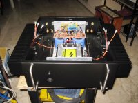
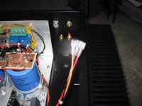
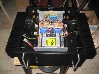
this is how i did it in my HB amp...
Attachments

said another way, every power rail lines must return to its source.....
however if the return point of the source is made into a common point,
then the requirement of the first line is met...
i so not see any confusion here...
In his imaginary amplifier builds power must not come from a power supply. It would be a lot easier accepting advice and constant correction if he'd ever actually done what he's such an expert on.
well, since i do not see any pictures of what he has done, i will keep
a neutral attitude....
a neutral attitude....
Star grounding techniques are now wrong?
how can it be wrong? i do it all the time, even in my tube amp builds...😉
- Home
- Amplifiers
- Solid State
- diyAB Amp The "Honey Badger" build thread