If you were to actually look at mattmcl's drawing you would see that he had joined all the returns a a common point on chassis ground. My post referring to this common point was to advise him not to attach these returns to chassis ground. This shouldn't be hard for a man of your "superior intellect" to figure out. Instead you chose this as a perfect opportunity to jump up on your soap box and exclaim I was wrong, when in fact I was correct, and you were showing your normal ignorance in not being able to use common sense in figuring this out, or you were flat out lying to try to show your intelligence.
The common point Prasi's diagram depicted was the star ground/ main audio ground on a supply of Ostripper's and my design. We designed the supply(i.e. we actually did something) so we are entitled to name this a star ground. You (who hasn't done anything) are not entitled to rename this connection to try to save face. The diagram is showing all pairs returning correctly to where they should go. All boards have all proper connections. I know this because all the boards in Prasi's drawing were my layouts, and we put together the drawing together(i.e. we actually did something).
I try to treat people with respect whenever possible. I try to explain things in simple English so new builders can easily grasp the basic principles. This may not always be perfectly accurate, but makes thing easier to digest by the inexperienced. You seem to feel you need to prove your superiority by constantly telling me everything is wrong and adding a bunch of abbreviations and algebra to your posts. This doesn't help clear up the confusion for anyone. A very wise man who I hold a lot of respect for(VZaichenko) has a quote from another very wise man in his signature. "If you can't explain it simply, you don't understand it well enough (c) Albert Einstein" You should think about this line before regurgitating the dictionary. When trying to explain the basics, you don't need to spout a bunch of confusing useless information, and others don't always need you to step in and add to the confusion.
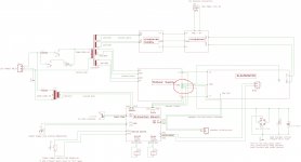
That layout & wiring diagram looks very good.
You have managed to keep all the Flow and Return pairs close coupled.
Even the speaker Return follows the Flow route from the amplifier and then follows the power routes from the PSU.
Well done.
The only exception is the single wire MAG to Chassis via the Disconnecting Network. This should only pass interference to the enclosure in normal operation.
I see no separated star ground and no need for one.
All the voltage references appear to be on the PCBs and thus no need for external voltage reference wiring.
Thanks Andrew,
It was made by Jeff only, I only made it more illustrative for myself so that I can understand as to which wire/connection goes where+added some legends.
reg
Prasi
That's where our reading differs.If you were to actually look at mattmcl's drawing you would see that he had joined all the returns a a common point on chassis ground.................
The drawing shows close coupled pairs.
Each of those close coupled pairs shows a Flow and Return for that specific current route.
None of these need to return to a common point. They don't, they return to their own source.
That's where our reading differs.
The drawing shows close coupled pairs.
Each of those close coupled pairs shows a Flow and Return for that specific current route.
None of these need to return to a common point. They don't, they return to their own source.
No matter how you twist the wording, star ground is not ideal directly connected to chassis ground. My diagram showed correct wiring techniques. Your "correction" was incorrect.
If you look at the schematic, there are many connections at the "star ground". Yes signal wiring returns to the amplifier board, but everything else returns to the "star ground". One return to the amplifier board hardly adds any merit to your argument. Amplifier return, speaker return, input return, ect. still all go to the "star ground". A nice design feature of a good supply is it has the "star ground" on board.
Mattmcl clearly stated that he didn't understand the schematic. If you felt the need to add some input, this would have been a perfect opportunity to explain something in simpler terms, not to add to the confusion with incorrect assertions.
Attachments
Audio GND channel separation vs. DC protection
I believe I walked into a trap when I installed DC protection modules in my recent builds... My Honey Badger is a stereo amp in a single chassis. I was careful to keep the audio GNDs of both channels fully separated from each other using separate ground loop breakers and separate DC protection units for each channel. However, the DC protection units are powered from the same helper PSU, so they share the same "0V" (or GND, if you want). This means that the audio GNDs of the two channels have a direct connection to each other via the power supply of the DC protection units. Aaaaargh!
I am pretty sure I am not the first one with this issue, and I am also sure there are some clever ideas how to clean this up. Any suggestions? Cheap and simple solutions, please 🙂 I would definitely prefer not to end up with two separate helper PSUs for the two DC protection units (I am currently using the 12 VDC which is conveniently available from my inrush limiter board).
Last edited:
I believe I walked into a trap when I installed DC protection modules in my recent builds... My Honey Badger is a stereo amp in a single chassis. I was careful to keep the audio GNDs of both channels fully separated from each other using separate ground loop breakers and separate DC protection units for each channel. However, the DC protection units are powered from the same helper PSU, so they share the same "0V" (or GND, if you want). This means that the audio GNDs of the two channels have a direct connection to each other via the power supply of the DC protection units. Aaaaargh!
I am pretty sure I am not the first one with this issue, and I am also sure there are some clever ideas how to clean this up. Any suggestions? Cheap and simple solutions, please 🙂 I would definitely prefer not to end up with two separate helper PSUs for the two DC protection units (I am currently using the 12 VDC which is conveniently available from my inrush limiter board).
I've been caught by the same issue in the past. This is why I designed our 21st Century Protection system with optically isolated circuits to completely isolate the control grounds from the amplifier grounds. http://www.diyaudio.com/forums/soli...1st-century-protection-board.html#post4110406
Hi Matthias,
the easiest way is a third star where both main PSU 0V stars and the auxiliary PSU 0V connect. You could also connect the chassis via a single ground loop breaker to this.
By this, you have to give up the idea of a true dual mono design. I don't have a clue if this matters?
Best regards!
the easiest way is a third star where both main PSU 0V stars and the auxiliary PSU 0V connect. You could also connect the chassis via a single ground loop breaker to this.
By this, you have to give up the idea of a true dual mono design. I don't have a clue if this matters?
Best regards!
Hi Matthias,
the easiest way is a third star where both main PSU 0V stars and the auxiliary PSU 0V connect. You could also connect the chassis via a single ground loop breaker to this.
By this, you have to give up the idea of a true dual mono design. I don't have a clue if this matters?
Best regards!
This third star ground leaves you susceptible to ground loops if you use a source with common audio grounds, which is almost always the case. The lifted grounds on the audio inputs helps with this issue, but it still can be a problem.
I've been caught by the same issue in the past. This is why I designed our 21st Century Protection system with optically isolated circuits to completely isolate the control grounds from the amplifier grounds. http://www.diyaudio.com/forums/soli...1st-century-protection-board.html#post4110406
Yep, I should've used your board. Stupid me, trying to save a few bucks by going the ePay route...
The amp sounds very good as it is. But I'd still like to clean this up so I can sleep better 🙂
This third star ground leaves you susceptible to ground loops if you use a source with common audio grounds, which is almost always the case. The lifted grounds on the audio inputs helps with this issue, but it still can be a problem.
Yes, I'm well aware of this. Might the related resistors on both boards be increased, if any hum problem occurs? If so, to which value at maximum?
Btw, are there any PCB's of your 21st Century Protection Board available from the DIYAudio store?
Best regards!
Yep, I should've used your board. Stupid me, trying to save a few bucks by going the ePay route...
The amp sounds very good as it is. But I'd still like to clean this up so I can sleep better 🙂
Cost is definitely an issue with our design. The solid state relays add up fast!
You may possibly be able to connect your amplifier grounds and control grounds through a high wattage 10 ohm resistor to act as a secondary loop breaker. Can you post a schematic of the protection system you are using?
Yes, I'm well aware of this. Might the related resistors on both boards be increased, if any hum problem occurs? If so, to which value at maximum?
Btw, are there any PCB's of your 21st Century Protection Board available from the DIYAudio store?
Best regards!
Most of Pete's designs switched to 10 ohm ground lift resistors. This seems to be the standard now in most.
The 21st Century systems are available through our website. Virtual Zero Audio - power amplifier products
Cost is definitely an issue with our design. The solid state relays add up fast!
You may possibly be able to connect your amplifier grounds and control grounds through a high wattage 10 ohm resistor to act as a secondary loop breaker. Can you post a schematic of the protection system you are using?
I may have the schematic somewhere in my workshop, will have to dig it out. In the meantime, here's a link to the units I used (rather basic easy-peasy stuff). I converted these stereo units to single channel (paralleled the two sides of the relay), and used one of those units for each channel.
You may possibly be able to connect your amplifier grounds and control grounds through a high wattage 10 ohm resistor to act as a secondary loop breaker.
Most of Pete's designs switched to 10 ohm ground lift resistors. This seems to be the standard now in most.
Both together will double the impedance of a possible ground loop, what might do it.
Thank you. I will have a look at it later. You don't wish to publish PCB data files, do you?The 21st Century systems are available through our website. Virtual Zero Audio - power amplifier products
Best regards!
I may have the schematic somewhere in my workshop, will have to dig it out. In the meantime, here's a link to the units I used (rather basic easy-peasy stuff). I converted these stereo units to single channel (paralleled the two sides of the relay), and used one of those units for each channel.
Another option, Matthias: Get two (one per protection board) cheap 12V 0.5A (or whatever it needs) wall-wart PSU's from a surplus dealer (I could recommend one to you, if you wish...), loot their boards and get these into your build.
Best regards!
I can email some Gerber files for some of the earlier designs (version 4). I've got quite a bit of time and money invested in the later design prototyping. I would prefer to try to recoup some of this with board sales of the later designs, so I'm not going to release them.
We ship all over the world for $15 USD. Boards normally arrive in Europe and Australia faster than into the US do to some customs issues.
Sounds promising, so far. The price of this protection board I can see at your homepage, I assume?
Best regards!
Best regards!
Another option, Matthias: Get two (one per protection board) cheap 12V 0.5A (or whatever it needs) wall-wart PSU's from a surplus dealer (I could recommend one to you, if you wish...), loot their boards and get these into your build.
Mmmmhhwmpf, well, that would work. But too much hassle for a bunch of crappy eBay boards, and I'm sure it wouldn't look very pretty 🙂
- Home
- Amplifiers
- Solid State
- diyAB Amp The "Honey Badger" build thread