I think AndrewT was refering to an small separate isolation transformer for the softstart circuit. I use small transformers for my control circuits, but I use a microprocessor to time everything.
I've read through your transformer building thread. Cool stuff! I'd like to try it some day.
I've read through your transformer building thread. Cool stuff! I'd like to try it some day.
How does one strike a balance between normally safe mains circuits and wiring whilst blocking dangerous directly powered circuits without any protection at all? At some point, I think the idea of intent has to enter the picture. Of course there will always be smart alecs who will try and skirt any rules that are put in place.
What to do? The only way I can see to allow normal good practice while blocking dangerous mains connections is to apply the rules selectively on the premise of merit and intent. Anyone who can write a straightforward rule that covers all situations is welcome to try. For now we only have our own good common sense to guide us.
One thing you can pretty much count on is that a desire to wire directly to the mains for purely cost savings is very probably both dangerous and stupid.
Switching supplies of the flyback variety normally isolate the supply with a transformer. So there is a safe option for switching power supplies.
-Chris
Anybody opening the cover on, or building mains connected equipment needs some basic safety gear on their bench at all times. While 240V product design used to be my profession I do not consider myself anal about safety. My list is;
a/ isolation transformer (2 100VA 45V toroidals connected secondary to secondary)
b/ dead-man switch, one hand must be on the momentary-on push button for power so I cannot accidentally zap my heart
c/ lamp tester (actually my dead-man switch with a lamp instead of shorting link in the lamp socket (these links are available in Australia))
d/ meter probes with the hook on the end like a CRO probe so I do not have to use 2 hands
e/ earth leakage circuit breakers in my workshop, just in case
With this stuff I am happy to work alone.
And of course, zero alcohol (ditto when I ride my bike)
So my comments about Softstart are really predicated on having appropriate safety gear and attitude.
John
Last edited:
Hi John,
And I do have that equipment, except for the panic off switch. I use a commercial isolation transformer. In that piece of equipment, there is also an AC mains leakage meter.
-Chris
And I do have that equipment, except for the panic off switch. I use a commercial isolation transformer. In that piece of equipment, there is also an AC mains leakage meter.
-Chris
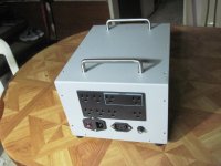
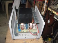
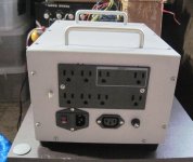
Very nice AJT
thaks, a fellow from the november hifi show in manila last year carted it away, so i ma making another one, about the same capacity....
Are you as a Moderator now telling us that the Forum Rules will prevent us discussing any Mains Powered project?yes, but you still have to connect the primaries to mains, and that is working with the mains isn't it?😱
Chris has shown fair rationale in #2422: While discussions on amps or other devices directly (without insulation) fed from the mains are a no-go here, discussions on power supplies and related things have to be allowed, because feeding, e.g., a Honey Badger from batteries doesn't make any sense.
Best regards
Best regards
Andrew,
By now you know very well that when a member of the moderating team is speaking as a moderator, they will use the symbol. Please do not attempt to provoke a situation that doesn't exist. I made a direct statement that covers how we handle these threads / posts. So chase me. BTW, I didn't use the symbol, so I'm posting mostly as a normal member.
-Chris
By now you know very well that when a member of the moderating team is speaking as a moderator, they will use the
symbol. Please do not attempt to provoke a situation that doesn't exist. I made a direct statement that covers how we handle these threads / posts. So chase me. BTW, I didn't use the symbol, so I'm posting mostly as a normal member.-Chris
Andrew,
By now you know very well that when a member of the moderating team is speaking as a moderator, they will use the
-Chris
Just because you can, doesn't mean you should 🙂
right on! Anatech!,Andrew,
By now you know very well that when a member of the moderating team is speaking as a moderator, they will use the
-Chris
my dear Andrew chooses to ignore rules when its convenient and engages in nit-picking them when its convenient.
reg
Prasi
To, Andrew remember the time when we had a spat abt using caps in apex thread....BTW I hold nothing against you, but what anatech is saying is right. My feeling...
I know there is gonna be a long and winding reply by Andrew, but i will choose to accept and be quiet😉..
AJT's post was two before yours.Andrew,
By now you know very well that when a member of the moderating team is speaking as a moderator, they will use the
-Chris
I replied to AJT's post.
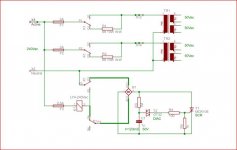
Circuit in post 2406 is a clever circuit ..but can get better with this modification .. this way ... even after a quick power failure the timer is reset ..
Thanks audiofan but it is not necessary to add a discharge path for the timing capacitor as you propose. Let me explain...
1/ When power is applied the timing cap is charged through the relay coil.
2/ When the charge on the cap reaches the Diac breakover voltage it conducts in avalanche mode (negative resistance) through the SCR gate and fully discharges the cap (at least down to 2 diode drops).
3/ The gate current triggers the SCR on and it conducts with only a single diode drop until the relay turns on. There is now no voltage across the SCR to re-charge the timing cap.
4/ Relay contacts P3 latch the relay ON until power is removed.
To further improve safety it is possible to use the relay contacts P3 and P4 to completely isolate the timing circuit and leave it floating. See the attached update....changes in bold.
John
Attachments
Hi Andrew,
-Chris
You most certainly did, and I didn't like the tone of that post so I replied. That post in response addresses your concerns I believe.AJT's post was two before yours.
I replied to AJT's post.
-Chris
AJT's post was two before yours.
I replied to AJT's post.
and i see no point replying to yours......

anyone asking about diacs.....https://www.google.com.ph/search?q=...cs&aqs=chrome..69i57&sourceid=chrome&ie=UTF-8
Johno, i tried your circuit in the 80's but was unhappy with the result,
the power traffo had mechanical buzz, i hope you have better luck with yours...😉
that is why i am back to plain jane resistor cum relay as mentioned
in the 1980 Audio article by Walter Jung about building an energy storage bank
for power amps....
too bad that i can not post that article here as i did not have permission
from the author to post the same.....
- Home
- Amplifiers
- Solid State
- diyAB Amp The "Honey Badger" build thread