Thanks audiofan but it is not necessary to add a discharge path for the timing capacitor as you propose. Let me explain...
1/ When power is applied the timing cap is charged through the relay coil.
2/ When the charge on the cap reaches the Diac breakover voltage it conducts in avalanche mode (negative resistance) through the SCR gate and fully discharges the cap (at least down to 2 diode drops).
3/ The gate current triggers the SCR on and it conducts with only a single diode drop until the relay turns on. There is now no voltage across the SCR to re-charge the timing cap.
4/ Relay contacts P3 latch the relay ON until power is removed.
Before the first coffe in the morning .... I should keep away from electronic.
Johno, i tried your circuit in the 80's but was unhappy with the result,
the power traffo had mechanical buzz, i hope you have better luck with yours...
sorry for the quick draw, mine was a different one but also using thyristors......
on second thought, i think your plan is sound, i might breadboard it and see for myself...
Thermal runaway
Didn't help with the diode transistor. That could help in case of a too high temp coefficient if the diode transistor is not mounted on the heat sink. But with both mounted on HS I have also to adjust the resistor values to finally end up in the same coefficient.
A solution I found in the book from Douglas Self "audio power amplifier design": to add a voltage source in series to R29/R30. But I hesitate to try it because I would rather like to understand why I have this problem at all where it seems to work for others.
I rather thinking of trying other (better) isolators for the power BJTs and Q13 since I am not too far away from thermal stability. I have also tried to mount Q13 directly on one of the power BJT, to no avail. Of course using thermal grease.
Also I tried to use an 2SC3503 instead of MJE340 but it gives same results.
Here my measured temp/Voltage (emitter-emitter Q18-Q21) values:
27°C/25mV
31.6°C/27.4mV
36°C/32.4mV
40°C/37mV
53°C/54mV
I am using silicone isolators, maybe I should try mica?!
As you increase the resistor from one side of the transistor's base, you'd also have to increase the other one by the same ratio, in order to achieve the correct Vce for biasing the cold output devices. Thus the Vbe multiplying factor will remain constant. Perhaps a second transistor, wired as a diode and also mounted on the heatsink, in the emitter lead of the first one would solve your problem?
Didn't help with the diode transistor. That could help in case of a too high temp coefficient if the diode transistor is not mounted on the heat sink. But with both mounted on HS I have also to adjust the resistor values to finally end up in the same coefficient.
A solution I found in the book from Douglas Self "audio power amplifier design": to add a voltage source in series to R29/R30. But I hesitate to try it because I would rather like to understand why I have this problem at all where it seems to work for others.
I rather thinking of trying other (better) isolators for the power BJTs and Q13 since I am not too far away from thermal stability. I have also tried to mount Q13 directly on one of the power BJT, to no avail. Of course using thermal grease.
Also I tried to use an 2SC3503 instead of MJE340 but it gives same results.
Here my measured temp/Voltage (emitter-emitter Q18-Q21) values:
27°C/25mV
31.6°C/27.4mV
36°C/32.4mV
40°C/37mV
53°C/54mV
I am using silicone isolators, maybe I should try mica?!
Last edited:
Can you provide some photos?Didn't help with the diode transistor. That could help in case of a too high temp coefficient if the diode transistor is not mounted on the heat sink. But with both mounted on HS I have also to adjust the resistor values to finally end up in the same coefficient.
A solution I found in the book from Douglas Self "audio power amplifier design": to add a voltage source in series to R29/R30. But I hesitate to try it because I would rather like to understand why I have this problem at all where it seems to work for others.
I rather thinking of trying other (better) isolators for the power BJTs and Q13 since I am not too far away from thermal stability. I have also tried to mount Q13 directly on one of the power BJT, to no avail. Of course using thermal grease.
Also I tried to use an 2SC3503 instead of MJE340 but it gives same results.
Here my measured temp/Voltage (emitter-emitter Q18-Q21) values:
27°C/25mV
31.6°C/27.4mV
36°C/32.4mV
40°C/37mV
53°C/54mV
I am using silicone isolators, maybe I should try mica?!

One mistake I perhaps made was not to press the power bjts sufficiently on the heat sink to reduce the silicone thickness. This is not possible by the screw only. Perhaps with the help of clamps I get a lower thermal resistance.
Sure
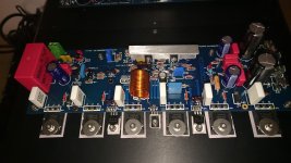
Actual design with Q13 between Q14/Q15:

You grouped Q13, Q14 and Q15 together. The diyAudio Honey Badger boards have them separated, with Q13 between two power devices (see photo). Could this lead to different thermal behaviour?
Attachments
You got it, Matthias! In Zymorg's construcion the Vbe transistor senses the temperature of the drivers, which almost certainly are much colder than the power devices.
Best regards!
Best regards!
Maybe try a "thermal bus bar" as shown in the HB build guide (you can download the PDF from the diyaudio store). This would easily allow you to 'skip' the drivers in your build.You got it, Matthias! In Zymorg's construcion the Vbe transistor senses the temperature of the drivers, which almost certainly are much colder than the power devices.
Best regards!
Also I tried to use an 2SC3503 instead of MJE340 but it gives same results.
Here my measured temp/Voltage (emitter-emitter Q18-Q21) values:
27°C/25mV
31.6°C/27.4mV
36°C/32.4mV
40°C/37mV
53°C/54mV
I am using silicone isolators, maybe I should try mica?!
Try to use higher hfe transistors for Vbe multiplier. Another thing: that it's not necessary to use any insulator for the fully insulated 2SC3503.
I use KSC2690, because it has hfe>300.
There are some type, which are designed especially to Vbe multiplier, such as 2SC4495, with very high hfe.
Sajti
My 2SC3503 is not insulated, the collector is connected to the housing. I don't think insufficient hfe plays a role here: R28=1.63V; R29=0.48V; R27=0.584V --> hfe~214
(R27=82; R28=2.2k; R29=680). 0.03mA Ib shouldn't make a significant difference with 0,74mA I(R28).
I also cannot imagine that a thermal bus bar helps because I already tried to mount Q13 directly onto one of the power devices - the result was worse than mounted between Q14/Q15. Seemingly the plastic housing has a higher thermal resistance than Power device->insulator->heat sink-> insulator -> Q13.
With 0.05mm Glimmer instead of silicone I could improve the compensation a little but still insufficient, see diagram:

Tomorrow I will try to mount Q13 very close to the power devices.
(R27=82; R28=2.2k; R29=680). 0.03mA Ib shouldn't make a significant difference with 0,74mA I(R28).
I also cannot imagine that a thermal bus bar helps because I already tried to mount Q13 directly onto one of the power devices - the result was worse than mounted between Q14/Q15. Seemingly the plastic housing has a higher thermal resistance than Power device->insulator->heat sink-> insulator -> Q13.
With 0.05mm Glimmer instead of silicone I could improve the compensation a little but still insufficient, see diagram:
Tomorrow I will try to mount Q13 very close to the power devices.
I've made this argument a few times. I think the sensor on top of the output device was developed when the output stage used To3 metal can devices............... I already tried to mount Q13 directly onto one of the power devices - the result was worse than mounted between Q14/Q15. Seemingly the plastic housing has a higher thermal resistance than Power device->insulator->heat sink-> insulator -> Q13...............
The plastic devices have too much insulation in my view.
I have suggested that a sot23 glued to the middle lead out of the output device gets closer to measuring the Tj and thus a better tempco for the Vbe multiplier.
Doug Self shows TO-126 packages mounted on the case of the plastic TO-3 and similar cases. Depending on the design of the output stage, the bias sense transistor should be mounted to the drivers.
A SOT23 stuck to the collector lead of any part would be difficult to attach without shorts to the terminals. If it releases under operation and something touches the collector lead, you could be picking up the pieces for a while. You're further ahead to use the Thermal Trak devices On Semi came out with.
-Chris
My 2SC3503 is not insulated, the collector is connected to the housing.
Try to get insulated version, if possible! They are better.
I don't think insufficient hfe plays a role here: R28=1.63V; R29=0.48V; R27=0.584V --> hfe~214
(R27=82; R28=2.2k; R29=680). 0.03mA Ib shouldn't make a significant difference with 0,74mA I(R28).
214 is not bad, but higher is better. My KSC2690s has hfe over 300, and they give better regulation comparing to the 3503, in my amplifier.
Try to put the Vbe transistors above the output devices. The warm air rising up, so the top of the heatsink has higher temperature.
Sajti
Try to put the Vbe transistors above the output devices. The warm air rising up, so the top of the heatsink has higher temperature.
I don't think so. As there's no convection within a solid body and the convecting air never gets as warm as, not to say warmer than the heat sink's surface, most supposedly the highest temperature is in the mounting area of the power devices.
Haven't measured it, though.
Best regards!
To me it sounds reasonable to put Q13 above the power devices. Cold air is comming from the bottom, heating up and air temp is rising as it goes upwards. Perhaps not a big difference but in case of doubt I would put it above the power devices, but very close to them.
A copper bar on which the power devices are mounted and this mounted again on the aluminium heat sink could also reduce delta temp.
However, I am still wondering how it is possible that others don't seem to have issues here. If I remember correctly, ostripper stated that he had even an overcompensated bias (something I encountered with same bias spreader circuit with another amp I built).
Sanken and a long time later Onsemi manufactured power devices with diodes integrated inside the package to allow for this quick repsonding tempco.
Onsemi named theirs NJL, but I think all but one complementary pair were discontinued.
I still have 18 pairs waiting for projects.
Onsemi named theirs NJL, but I think all but one complementary pair were discontinued.
I still have 18 pairs waiting for projects.
Sanken and a long time later Onsemi manufactured power devices with diodes integrated inside the package to allow for this quick repsonding tempco.
Onsemi named theirs NJL, but I think all but one complementary pair were discontinued.
I still have 18 pairs waiting for projects.
That's certainly the best option but I don't want to buy 12 new power devices...
I don't think so. As there's no convection within a solid body and the convecting air never gets as warm as, not to say warmer than the heat sink's surface, most supposedly the highest temperature is in the mounting area of the power devices.
Haven't measured it, though.
Best regards!
Try to do some measurement! It's better to mount above than side by side. But it must close of course.
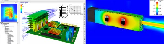
The convecting air is not as warm as the heatsink, but it's not cooling donw the heatsink as much as where it's cold. Check out the right side of the picture attached!
This is mesurement of the heatsink with left to right forced cooling. The temperature is significant higher at the output of the air.
Sajti
Attachments
Last edited:
and that is why you would mount the devices in an asymetrical arrangement to try to equalise the interface temperature of the devices.
We do the same for passive sinks. Move the lower device towards the cold/lower end and give the upper device more heatsink to work with in the warmed air.
We do the same for passive sinks. Move the lower device towards the cold/lower end and give the upper device more heatsink to work with in the warmed air.
- Home
- Amplifiers
- Solid State
- diyAB Amp The "Honey Badger" build thread