Renron,
Nice case, very good job.
However, with these swiss cheese VAS heatsinks you are asking for trouble in the long run. The whole area of the transistor must be heatsinked evenly. Somehow bolts got loose on my VAS transistors and although when cool these still measured well they did not perform well when hot.
cheers,
Thanks Janusz,
I appreciate the tip on the bolts becoming loose. I used aircraft nuts (nylock)
on the back side that you cannot see. Even with heat cycling they won't become loose.
No disrespect intended what so ever. However, I don't agree with your theory that the transistor heatsinks are not distributing heat properly. I could be wrong thou!
If the heatsink is a solid piece of aluminum (as most are) the heat is trapped in the center of the transistor by the washer and bolt / nut. Heat is mostly transferred from the edges, a solid heatsink does not cool as quickly as a perforated one. Cooling the transistors is the main function of the heatsink.
After 3 hours of music, they were cool to the touch, and the power transistors were barely warmer than room temp. Lots of ventilation.
OS / Andrew T, as long as the VAS transistors stay cool, do you see a problem with my implementation?
Thanks to ALL for the input.
Ron
RenRon,
looks very nice! I like the silkscreened (?) text on the front panel! I'm very curious about your impressions of the Honey "Bad ***" Badger.
Where did you get the power button? I'd like to use something like that in my amp. How is the light inside it powered?
Text on front is laser engraved on the polyester powder coated face and top. I wanted the print much smaller but there was a miscommunication and that's what I got. It was obnoxious until I stained the raw aluminum with acrylic ink from my wife's art supplies. It is much more subtle than the pictures show, in some light it disappears completely. weird.
The switch is from Amazon http://www.amazon.com/gp/product/B005LEOH0E/ref=oh_aui_detailpage_o03_s00?ie=UTF8&psc=1
decent quality or I would not have used it. It's light is powered by the rectifier from the speaker protection board, it is a dim blue, not a nuclear fusion hot blue. It matches my other equipment well.
Ron
Thanks Janusz,
I appreciate the tip on the bolts becoming loose. I used aircraft nuts (nylock)
on the back side that you cannot see. Even with heat cycling they won't become loose.
No disrespect intended what so ever. However, I don't agree with your theory that the transistor heatsinks are not distributing heat properly. I could be wrong thou!
If the heatsink is a solid piece of aluminum (as most are) the heat is trapped in the center of the transistor by the washer and bolt / nut. Heat is mostly transferred from the edges, a solid heatsink does not cool as quickly as a perforated one. Cooling the transistors is the main function of the heatsink.
After 3 hours of music, they were cool to the touch, and the power transistors were barely warmer than room temp. Lots of ventilation.
OS / Andrew T, as long as the VAS transistors stay cool, do you see a problem with my implementation?
Thanks to ALL for the input.
Ron
What I meant was that the whole area of transistor's metal section should be on a heatsink and from your photos it looks that some parts of VAS transistors may be covering holes and that could create problems over time. Holes are OK as long these are not under transistors. If you are certain that they are not then all is fine.
cheers,
Janusz,
You are correct, the heatsink has uniform holes underneath the transistors. I understand your point. It is a valid one. I have an A/B thermal epoxy compound that is designed for permanent transistor to heat sink applications. Thinking of using this to fill in the holes underneath the transistor, not to permanently attach the transistors to the heat sinks.
Arctic Alumina Thermal Adhesive
Could be the best of both worlds. 😀
Ron
PSU module wired up, soft starter completed and function tested.....
An externally hosted image should be here but it was not working when we last tested it.
An externally hosted image should be here but it was not working when we last tested it.
An externally hosted image should be here but it was not working when we last tested it.
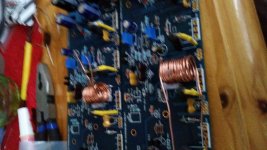
does these inductors looks ok ?
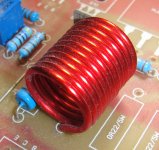
L1 inductor, 1.5µH - 14-16 turns 18ga. enameled copper 12.5 -15mm diameter 🙂 BOM
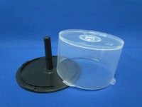
make it tight take your time sir, should look like this image close "example" , I use a pole from a CD container I drill one side to hold the wire then begin turning but tight really tight as possible 🙂 and will look good
note: I use 15AWG because it retains the shape better in my case 😛
Regards
Juan
Attachments
Last edited:
L1 inductor, 1.5µH - 14-16 turns 18ga. enameled copper 12.5 -15mm diameter 🙂 BOM
make it tight take your time sir, should look like this image close "example" , I use a pole from a CD container I drill one side to hold the wire then begin turning but tight really tight as possible 🙂 and will look good
note: I use 15AWG because it retains the shape better in my case 😛
Regards
Juan
Best "trick" of the week !! Thank you 😎😎 !!!
OS
Parasitic Capacitance of wound coils.
I stretch my single layer coils slightly after winding.
Just enough to get a 0.1mm to 0.2mm gap between the turns.
I do this thinking it may reduce the parasitic capacitance, but does it?
What is the best way to wind a coil to minimise the parasitic capacitance?
I stretch my single layer coils slightly after winding.
Just enough to get a 0.1mm to 0.2mm gap between the turns.
I do this thinking it may reduce the parasitic capacitance, but does it?
What is the best way to wind a coil to minimise the parasitic capacitance?
I stretch my single layer coils slightly after winding.
Just enough to get a 0.1mm to 0.2mm gap between the turns.
I do this thinking it may reduce the parasitic capacitance, but does it?
What is the best way to wind a coil to minimise the parasitic capacitance?
I have no clue about the capacitance but stretching the coil lowers the inductance.
So 0u8H becomes 0u7H.
What tolerance are you working to?
I just go by on line calculators. I'm not sure what tolerance they are striving for but length seems to make a huge difference in inductance. It's not an issue if you have the space but the extra bulk can be quite substantial if you are trying to finish at 1.5mH on a compact board.
If you want to minimise resistance then use a "Wheeler" shaped coil.
If you want simplicity use a single layer coil.
But that long coil increases resistance.
If you want simplicity with lowish resistance, then use a very large diameter mandrill/bobbin.
The greater the diameter:length ratio, the lower the resistance, upto about 4:1
That 4:1 ratio is in there, when you look at a Wheeler shaped coil.
For a Thiele Network consisting of the two parts specified By N.Thiele, then you will find that tolerances can be very wide. It's why the "nearly universal" Zobel works with 100nF+10r. That will still work even if the tolerances were +-10% on both components.
It's much the same for the other half of the Thiele Network. +-10% is not a problem.
Resistance can be a problem, if output impedance rise at high audio frequencies is critical.
Similarly parasitic capacitance can be a problem if RF attenuation of interference coming in on the speaker leads is critical. Very few fit RF attenuation to all the cable entries.
Locate it away from the amplifier and locate it away from metal panels (including the floor panel).
Half way along the speaker leads is usually a fairly good compromise between distance from the PCB and distance from metal panels.
If you want simplicity use a single layer coil.
But that long coil increases resistance.
If you want simplicity with lowish resistance, then use a very large diameter mandrill/bobbin.
The greater the diameter:length ratio, the lower the resistance, upto about 4:1
That 4:1 ratio is in there, when you look at a Wheeler shaped coil.
For a Thiele Network consisting of the two parts specified By N.Thiele, then you will find that tolerances can be very wide. It's why the "nearly universal" Zobel works with 100nF+10r. That will still work even if the tolerances were +-10% on both components.
It's much the same for the other half of the Thiele Network. +-10% is not a problem.
Resistance can be a problem, if output impedance rise at high audio frequencies is critical.
Similarly parasitic capacitance can be a problem if RF attenuation of interference coming in on the speaker leads is critical. Very few fit RF attenuation to all the cable entries.
Do not put the coil part on the amplifier PCB.at 1.5mH on a compact board.
Locate it away from the amplifier and locate it away from metal panels (including the floor panel).
Half way along the speaker leads is usually a fairly good compromise between distance from the PCB and distance from metal panels.
Last edited:
If you want to minimise resistance then use a "Wheeler" shaped coil.
If you want simplicity use a single layer coil.
But that long coil increases resistance.
If you want simplicity with lowish resistance, then use a very large diameter mandrill/bobbin.
The greater the diameter:length ratio, the lower the resistance, upto about 4:1
That 4:1 ratio is in there, when you look at a Wheeler shaped coil.
For a Thiele Network consisting of the two parts specified By N.Thiele, then you will find that tolerances can be very wide. It's why the "nearly universal" Zobel works with 100nF+10r. That will still work even if the tolerances were +-10% on both components.
It's much the same for the other half of the Thiele Network. +-10% is not a problem.
Resistance can be a problem, if output impedance rise at high audio frequencies is critical.
Similarly parasitic capacitance can be a problem if RF attenuation of interference coming in on the speaker leads is critical. Very few fit RF attenuation to all the cable entries.
Do not put the coil part on the amplifier PCB.
Locate it away from the amplifier and locate it away from metal panels (including the floor panel).
Half way along the speaker leads is usually a fairly good compromise between distance from the PCB and distance from metal panels.
I'm trying to find a picture of a Wheeler shaped coil but not coming up with anything useful. What shape is it?
Most Amplifier designs you find here have the inductor on board and it's always too crowded for my liking. I remember seeing it done as you suggest in older competition car amps (eg. Phoenix gold MS250). I thought it was to dissipate heat better in those as you could literally fry eggs on those amps.. Are you suggesting it for noise?
Last edited:
the coil part is roughly square, there's actually a 10:9 ratio in there, but I can't remember which is 10 and which is 9.
The overall diameter is 4 times the width/height of the coil.
That makes the bobbin 2 times the width/height of the coil.
I gave the design data in the spread sheet that I have posted a few times.
Try searching Wheeler's formula. There are a number of inductor calculators that use Wheeler as one of their options.
the coil part is roughly square, there's actually a 10:9 ratio in there, but I can't remember which is 10 and which is 9.
The overall diameter is 4 times the width/height of the coil.
That makes the bobbin 2 times the width/height of the coil.
I gave the design data in the spread sheet that I have posted a few times.
Try searching Wheeler's formula. There are a number of inductor calculators that use Wheeler as one of their options.
Thanks.
- Home
- Amplifiers
- Solid State
- diyAB Amp The "Honey Badger" build thread