I am still filling out some v2.4 boards and the only thing different from what I have found here on site is the need for a BAV21 diode (D3) and one 820R resistor (R24) changed to 1.2K but...so much has been written you may find some suggested changes in these 110 pages that suit your particular build. Oh, and I'm using Mouser 280-CR5-0.22-RC resistors as I could not find the Noble Resistor types (power resistors - R43-R50)
If v2.4 is no longer available then may be it's time to come up with a v2.5 upgraded design including on board current limiter for those who'd like to have it in.
I would also suggest 1mm holes, 10mm hole distance for main filtering on-board caps, zoebel resistor and emiftter resistors pin layout allowing use of caddocks and SYMETRICAL (mirror image) board pairs.
jdg123,
on EBay you can get 0.33 ohm or 0.1 ohm non-inductive resistors. Alternatively, you may try Michael Percy. He's got non-inductive Mills MRA-5 .22/5W at $3.50 each.
Using standard wirewound resistors may be a bit tricky but should work in most cases. If one gives up a current limiter then 0.1 ohm is good enough with matched output transistors and inductance is lower. That's what is often practiced in Australia by kit makers.
Mouser has BAV45a, which is better than BAV21. I have created a small stock of these for future needs.
cheers,
I didn't use non-inductive resistors for the outputs. Is this standard practice that many people believe is worthwhile over traditional wirewounds?
Also, when I look at the Mills MRA-5, I see that they are a "non-inductive wirewound". How do they make wirewound resistors with so little inductance? Is this more of a marketing term or do they truly have less inductance? (I am not really looking forward to taking my amp apart and replacing with these.)
Here is a possible supplier for mills MRA-5 I found in Canada: Mills MRA-5 Resistors
Ordinary resistors in most cases should work. It's only chances of getting oscillations under some conditions vary depending on inductance levels.
No wirewound resistor is non-inductive. My guess is that different wire materials are used so the number of windings differs hence inductance varies as well.
cheers,
No wirewound resistor is non-inductive. My guess is that different wire materials are used so the number of windings differs hence inductance varies as well.
cheers,
Ordinary resistors in most cases should work. It's only chances of getting oscillations under some conditions vary depending on inductance levels.
No wirewound resistor is non-inductive. My guess is that different wire materials are used so the number of windings differs hence inductance varies as well.
cheers,
It's correct to say no resistor is non inductive. You can get very low inductivity in a wirewound resistor using special way how to wind, as a bifilar.
I didn't use non-inductive resistors for the outputs. Is this standard practice that many people believe is worthwhile over traditional wirewounds?
Also, when I look at the Mills MRA-5, I see that they are a "non-inductive wirewound". How do they make wirewound resistors with so little inductance? Is this more of a marketing term or do they truly have less inductance? (I am not really looking forward to taking my amp apart and replacing with these.)
Here is a possible supplier for mills MRA-5 I found in Canada: Mills MRA-5 Resisto,rs
From the common datasheets inductance of wirewounds at values of below 0.26R is not a concern because swamped by traces and leads which are more. And, even 0.33R is of very little practical concern--probably none.
Last edited:
The lowest inductance is to be had by using a winding technique called Ayrton-Perry. Presumably named after the guys that devised it. Try Googling "Ayrton-Perry winding". I bought some from Digikey for an amplifier project.It's correct to say no resistor is non inductive. You can get very low inductivity in a wirewound resistor using special way how to wind, as a bifilar.
Keith
OS?
I am trying to be very, very careful with this Honeybadger build so I am asking what OS had in mind within his build guide (DIYaudio Class AB amplifier - "options.txt") for a sort of "pre-test" of the drivers to keep from blowing up the outputs accidently upon start up.
IT says in that text found under --general construction tips --point C, : "Build the amp totally EXCEPT for the output stage TO-3P/TO-247 devices, DO NOT solder in R36. Instead temporarily solder 2 - 68R reisstors between R40 and R37 and the long output trace that is hooked to L1."
Pictured are a pair of (at the moment) unsoldered 68R resistors running from R40 and R37 to a lead of a 0.22R that is soldered onto the large via that L1 is soldered to. I think this is right. If this is what OS had in mind please indicate. I'm not adventurous and my understanding is slight...
Also in point C, it says: "When powering up for the first time either use the 2 fuse safety resistors (R53 and 54), or solder 2 "sacrificial" 10R 1.4-1/2W risistors to the V+ and V- terminals (after the fuses)."
___To be sure then, it means the boards will work and be safe with nothing in the fuse holders if the R53 and 54 resistors are soldered in? R53 , R54 are 22R; this seems like it might change the readings/power - it seems like the fuses should be in place too...
Later in the same point C, it advises: "Adjust R30 for +/- .55V "on" resistors R34 and 35...output should just be a few millivolts."
____Should "on" resistors say "across" resistors R34 and R35?
As a complete neophite I need to be sure where to place my probes for the reading. To me "on" means to clip red to the resistor (and which end is at question to me) and black to ground..."across" means to clip both probes to the ends of the resistor. I told you I was unsure/new 😕
___I have the same kinda worry for the last sentence: "...output whould be a few milivolts" ___This means to me, clip (red) on to the "output" fast-on (and black lead to ground) to read mV?
I have been successful in a few previous projects by just plowing ahead but I also have made some real ugly beginner mistakes and then had to frustrate some of you kind fellows in asking questions to hunt down the issues.
I know I must ask questions and hate to ask such basic ones but...I'm trying to get it straight here and throw myself at the mercy of the the good fellows of this forum.
Attachments

(below) is what I meant.
"RT1 / RT2" form a small class A amp and the center point is fed
to the output - feedback resistor.
In this form the amp will draw just 40-50ma per rail (If that).
Emitters of the 2 drivers can be set to .5 - .6 V (each - 1.1-1.2v total)
referenced from output.
when you do put your output devices in , they will be underbiased.
And , unless they are defective ... they will not burn up !
OS
Attachments
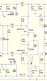
If you want to go this way then do not solder in R36 (C20 may be in or out). Solder 68 resistors between emitters of Q14 and Q15 to the output path. Get rid of R53 and 54. These will catch fire if fuses blow. You do not wat it happen with your boards mounted in a closed case. Instead of fuses solder 10-12ohm 1W resistors. Before applying power with your PS in series with 100W globe set multiturn pots as recommended.
After applying power set current to LTP to the required value. I have ss9014D so I set it to 3.2mA (voltage drop across R14=2.2k is to be about 7.1V), then set offset to ZERO (R17). Now turn R30 to get voltage drop of about 1V to 1.1V (no more than 1.1V) across both 68 ohm resistors, that is between drivers' emitters - Q14 and Q15. I was happy with 1.05V. Voltage drop across R34-35 should be ZERO.
If you use 2sa transistors as drivers with Hfe of 150 plus change R29 to 560 ohm. You may also change R12 to 6.8k and R13 to 6.6k - 8.2k. I have 7.5k for R13 and C5 is nominal 100uF/50V (actually 90uF measured). I have also reduced R2 to 221 low noise and increased C2 to 470-560pF. R24=1.2k, C7=82pF and C8=390pF. But do all that before tests.
If everything is fine, globe dimmes to blackness, temporary resistors did not catch fire then keep it on for 10-15 minutes, disconnect, desolder temporary resistors, solder in R36, C20 and power transistors, place fuses in fuse holders, check boards for soldering problems. If none and heatsinks bolted to transistors power up the module via a 100W globe and see what happens. If there is no fire, trafo is quiet, globe dimms check current to LTP, then zero offset and finally set bias to read about 15-18mV between TP1 and TP2. If your emitter resistors are .22 ohms. Keep the amp on for 20 min, check if readings do not exceed 18mV and disconnect. Remove globe from the line, plug in again and redo the settings with bias now to be about 50-60mA. I set it to 60mA (26mV between TP1 and TP2 with 0.22 ohm emitter resistors).
cheers,
Last edited:
My 5171, 1930 do HFE ~100 but otherwise behave as authentic.If you use 2sa transistors as drivers with Hfe of 150 plus. . .
Thanks OS and Janusz, especially you OS for including such great graphics in your build guide. The map of the tracings in both black and white as well as the one in color, really help me to understand how the parts of the board relate to the schematic.
I'm gaining on it (an understanding of this amp build), due in large measure to the patience and generosity of you who respond to my beginner questions.
Thanks! 😀
I'm gaining on it (an understanding of this amp build), due in large measure to the patience and generosity of you who respond to my beginner questions.
Thanks! 😀
Thanks OS and Janusz, especially you OS for including such great graphics in your build guide. The map of the tracings in both black and white as well as the one in color, really help me to understand how the parts of the board relate to the schematic.
I'm gaining on it (an understanding of this amp build), due in large measure to the patience and generosity of you who respond to my beginner questions.
Thanks! 😀
I use this as my "proof" (color overlay) on all my amps. I can see the "flow"
of the circuit. It all has to "come together" (concept/simulation/layout).
I'm up to 7 amps in my thread - all work ...first time !
I did get the badger right in the first version... (1.1)
The "badger" is when I first used my "anal" star grounding 😀 , I
still use "badgertech" on my new amps.
OS
UMS and the TO-264...
Just a heads-up to any other beginners out there considering the MJL2193/4 for outputs (as that alternate output transistor has popped up a few times in this thread...): the package shape/size (TO-264) will not work with a predrilled/taped UMS case.
It's not a big deal, but had I paid attention I could have saved myself a few hours of putting holes in the wrong position as I went straight away to marking and drilling the UMS postions...🙂
Replacement for 1N5408
Hey everyone,
First timer, so apologies for ignorance!
The BOM calls for MURS320/1N5408 for D4, D5, D8, and D9.
Now, I happen to have a baggie full of MUR460G handy (600V, 4A). The BOM says any suitable 3A rectifier will work, so I assume this is a good replacement, right?
Comparing datasheets, there are some notable differences (1kV vs 600V reverse voltage, 200A vs 110A peak surge current, etc). However, the differences seem to be largely over-designed anyway.
For the flyback diode specs, the forward current and forward voltage are comparable between the two.
Any thoughts?
Thanks very much!
MUR 460 would be good for even "armageddon" EMP !!
PS - overkill for any expected voice coil "assaults" ! 😀
edit - the non-connected 12" isobaric sub (2 subs - face to face)will output <1 A ...
OS
PS - overkill for any expected voice coil "assaults" ! 😀
edit - the non-connected 12" isobaric sub (2 subs - face to face)will output <1 A ...
OS
Last edited:
Hi!
I've just placed an order for the boards to built this great amp kit, but I'm wondering anybody here could recommend a kit for a preamp/switcher to use with this amp? One that as a phono/riaa stage would be a plus. 😀
I've just placed an order for the boards to built this great amp kit, but I'm wondering anybody here could recommend a kit for a preamp/switcher to use with this amp? One that as a phono/riaa stage would be a plus. 😀
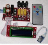
PGA2311
There are 2-3 vendor's for these kits. (below)
I think the >59$ one has the better PS/layout.
They spec out REAL good (google the PGA2311).
I am willing to try this for one of my amps (either badger or slewmaster).
😎😎 remote + digital readout ...
OS
There are 2-3 vendor's for these kits. (below)
I think the >59$ one has the better PS/layout.
They spec out REAL good (google the PGA2311).
I am willing to try this for one of my amps (either badger or slewmaster).
😎😎 remote + digital readout ...
OS
Attachments
drain the caps?
Hi all,
Just getting back to the amp after a long break and had a nasty reminder of how long caps can stay charged!
Once the amp is built in total will there be a built in drain on the caps?
I think that was the secondary purpose of the LEDs in the design yes?
Please advise, I don't want to make sparks again!
- Home
- Amplifiers
- Solid State
- diyAB Amp The "Honey Badger" build thread