Thanks Danielwritesbac, for the clarification on LEDs. I have yet to find someone (else) promulgating this needed perspective. It is best to test!
need to know basics...
Way back on page one, a question was put forth about the voltage rating for caps C7 & C8 (or rather the need for silvered micas 3V- 500V - and that 3V thing is confusing to a literal guy like myself 🙂. I gathered from the post that 120V may happen and ratings of 200V should "do"...I have put polystyrene caps in place which I had on hand and which are rated at 160V but now I am having second thoughts. What am I risking here?
Second question: has the recommended value of R24 been changed to something like 1.2K (from 820R)? This seemed to be put forth in conjunction with the use of the BC diode (BAV21) on the new v2.4 boards...I don't understand.😱
I'm still pretty new (my second amp build) so anything equivocal in postings leads me to ponder...
160V caps are OK, however in this application silver mica is best as it is extremely stable and does not change its characteristics with time. It might also have lower inductance.
I have R24=1.2k while C7-8 are 81pF and 390pF.
cheers,
I have R24=1.2k while C7-8 are 81pF and 390pF.
cheers,
Silver mica tend to be quite large for the capacitance they have. They also tend to have wide spaced lead outs.160V caps are OK, however in this application silver mica is best as it is extremely stable and does not change its characteristics with time. It might also have lower inductance.
I have R24=1.2k while C7-8 are 81pF and 390pF.
cheers,
These physical characteristics suggest they cannot be low inductance.
In relation to capacitance I suspect they are high inductance.
Film caps are smaller and have closer pin pitch.
Ceramic have much smaller size and much lower pin pitch especially in smd. Have you seen a 100pF 402 package NP0?
I've burned out a bunch of fuses now trying to warm up my first honey badger. I thought I fixed the problem earlier by replacing the 3 output transistors on the negative half of the output. After desoldering them I found that one exhibited a short between its C and E pins. After replacing these three transistors with fresh ones that tested well on my DMM, I powered it up, and all was going so well. I monitored the output offset, which I was able to keep at 0.000V while bringing the bias up. At first the voltage between TP1 and TP2 (using a single DMM hooked to those two points) was close to zero. I adjusted R30 until I had a few mv. I gradually increased it, letting the amp warm up for a minute or so between adjustments. Once I adjusted to see 20mv, I let it warm up further, and then the value started dropping steadily down to 16mv before I adjusted R30 to bring it up to 20mV again. At this point both fuses (slow blow 4A) blew simultaneously and a little magic smoke appeared near Q18. I noticed that the schematic shows 0.22 ohms for R43-48, but mine are measuring about 0.3 or 0.4 ohms each in circuit. Should I target a different reading across TP1 between TP2 due to this difference in resistance?
Any suggestions of what to replace or how to adjust this thing properly?
Any suggestions of what to replace or how to adjust this thing properly?
Most DMM's have trouble reading acurately at that low of OHMS. They will usually read .3 or .4 ohms just shorting the leads together. I don't think that's your problem. Why not set it at about 10mv and then take some readings and post them here so someone can point you in the right direction? It's likely that something else is wrong.
I have assembled again my first HB module, replaced VAS heatsink with a larger one as in the other module, connected it to PS with globe in series with the toroid. Globe is now 100W so the toroid's secondary winding AC voltage drops only by 4V with bias set to 45mA. I set LTP current to 3.1mA, which is apparently optimal for ss9014s. This way VAS current is also a bit lower. Anyway, so far with globe in series it seems to be very stable and holds onto 17.5mV between TP1 and TP2 with .18 ohm emitter resistors.
AndrewT,
My silver micas are roughly the same size as polystyrene caps. They are thinner and a bit boxy, while polystyrene are cylindrical so thicker and are constructed like a coil so their inductance is higher and therefore they are not used in high frequency circuits.
My micas have 8-9mm long bodies with pins about 6mm apart. Silver micas are are used in radio circuits and are often designed to have very low inductance for that reason. In the past silver micas used to be larger. I still have some I used in 1980s and 180pF/500V was about 16mm wide and 10mm high but very thin. I bought these from our local RS and apparently these were designed for radio frequency applications but I used them for not so high HF filtering.
SMD caps generally have lower inductance and SEMCO MIN and MCM silver mica caps have very low inductance as have been designed to work at gigaHertz frequencies. I have never heard of polystyrene caps being used at high radio frequencies although in SMD format they might have low inductance. Have never investigated as here we are not using SMDs.
cheers,
Question about OS construction notes
If anyone can help clarify some instructions, I'd be very happy.
Instead of focusing on my one not-yet-functioning amp, I'm trying to attempt the power-up sequence/method proposed in OStripper_notes.txt. Specifically I've managed to get 2 amplifier channels each running with output transistors Q16-21 and R36 uninstalled, but with a 68 ohm resistor between the C and E pins on Q20 and similarly between the C and E pins on Q17.
With this setup I feed in a sine wave and see an amplified sine wave on the output!!!
I have a bunch of DMMs and a scope. So far I've adjusted R7 to get 8.25 volts across the two R14 leads, so I think my CCS is good. I see around 0.5v on each of the 22ohm input rail current measurement resistors R53, an R54. I see about 2V across C9 (i.e. between R34 and R35).
Since I blew out fuses and fried my output transistors on an earlier attempt, I'd like to know exactly what to do with the R30 bias adjustment before installing the output transistors, R36, and the fuses). OS suggested "adjusting R30 for +/- .55V on R34 AND R35". Does this mean .55V across the two leads on R34, and then 0.55V across the two leads of R35, or does it mean 0.55 volts across C9 ? Is this with or without R36 installed? When I adjust R30, I don't see more than a couple mV on either R34 or R35, and I see 2V between the two resistors (i.e. across C9).
what do you mean .... R36 uninstalled .... leave it open circuit .. or .. short circuit with a piece of wire ????
what do you mean .... R36 uninstalled .... leave it open circuit .. or .. short circuit with a piece of wire ????
I left it open, no jumper in its place. Also, I had a typo earlier. To bypass the output stage I put a 68 ohm resistor between the B&E pins on Q20 and Q17.
Also, FYI, this is the OS note I was referring to:
C. Build the amp totally EXCEPT for the output stage TO-3P/TO-247 devices, DO NOT solder in R36. Instead temporarily solder 2- 68R resistors
between R40 and R37 and the long output trace that is hooked to L1. This will turn your drivers into the outputs !!! When powering up for the
first time either use the 2 fuse safety resistors (R53 and 54) , or solder 2 "sacrificial" 10R 1/4-1/2W resistors to the "V+ and V-"
terminals (after the fuses). Adjust R30 for +/- .55V on resistors R34 and 35 ... output should just be a few millivolts. This will insure
that the outputs are non-biased when they are installed.
up to this point looks good ... then set R30 ( output bias 500R ) to ge MINIMUM voltage across C9.
With the pair of 68 ohms in place you should have amplification ( output signal ) an be able to get bias set for LTP (Q2 Q1 ) and correct voltage across R14
You should also be able to set mean output voltage to zero ( ajusting R17 ) to get zero volts at output terminal ( measure with your voltmeter set on DC VOLTS ) with no signal at input .
Temporarily replace (tack) 2 68R's from Q14/15 emitters INSTEAD of R36 (150R) to the main OP inductor (or any point of the output trace).Does this mean .55V across the two leads on R34, and then 0.55V across the two leads of R35, or does it mean 0.55 volts across C9 ? Is this with or without R36 installed? When I adjust R30, I don't see more than a couple mV on either R34 or R35, and I see 2V between the two resistors (i.e. across C9).
This will have the drivers create .55 - .6 V across each of these 68R's
(1.1-1.2V total).
This voltage is about where your typical OP device will start to conduct.
.... 2V across C9 is also correct ... 🙂
If you are "gunshy", replace the 150R and just solder in one tested pair of
OP's. You will be slightly underbiased , decrease trimmer resistance to
get 12 mv at the OP re (.22R) ... all your remaining OP's will be the same.
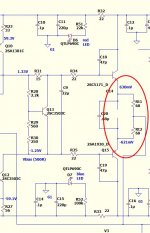
I use this technique on ALL my OEM amp repairs. (below) is example schema.
OS
Attachments
When you are redy to fit output transistors I recomand this technique:
1- Make sure heatsink is clean ..no dent.. no burr
2- Mount transistors on heatsink with hardware and bend leads to fit with PCB... make sure all transistors lay flat on heatsink and are using same type of heat transfer stuff. (contact between transistors and heatsink is critical ... thermal resistance must be as low as possible)
3- With all 9 transistors in place you should be able to put PCB in place with a very little effort. (free fit)
4- Using an ohmeter check insulation between heatsink and every transistors.... should read '' infinite '' on any lead of any transistors
5- Put pcb in place ..if there is extra hardware put it in place ... then the last thing to do is to solder the 27 leads.
According to me it is the best way to go .... solder will have minimum mechanical stress and transistors the best fit with heatsink.
Last edited by a moderator:
OK, my first HB (two boards) is operational. I thought I have fixed problems with soft start unit but it worked only a short time and 68 ohm/10W resistor burned, relay coil is probably gone as well so it is without a soft start.
This afternoon I listened for over one hour to music in an active system. So HB got frequencies above 750Hz, 90Hz to 750Hz went to lateral mosfet amp, below is Rythmik Audio 15"| 75mm v.coil servo 600W sub. HB has no current protection circuit yet, only speaker protection.
Noise and hum levels depend entirely on positioning of cables. I have managed to get it below 200uV but it can be lowered. Most of my cables are just hanging.
Sound is very clean and stereo image quite wide, notably wider than with Mimesis. I need to build another two modules to have everything above 80-90Hz played by HB to get it sound or just amplification with very little coloration.
cheers,
OK, my first HB (two boards) is operational. I thought I have fixed problems with soft start unit but it worked only a short time and 68 ohm/10W resistor burned, relay coil is probably gone as well so it is without a soft start.
This afternoon I listened for over one hour to music in an active system. So HB got frequencies above 750Hz, 90Hz to 750Hz went to lateral mosfet amp, below is Rythmik Audio 15"| 75mm v.coil servo 600W sub. HB has no current protection circuit yet, only speaker protection.
Noise and hum levels depend entirely on positioning of cables. I have managed to get it below 200uV but it can be lowered. Most of my cables are just hanging.
Sound is very clean and stereo image quite wide, notably wider than with Mimesis. I need to build another two modules to have everything above 80-90Hz played by HB to get it sound or just amplification with very little coloration.
cheers,
For even less coloration, if full bandwidth use, the inverting input coupler can be 220u||220u||4.7n (instead of 220u||100n on the schematic).
You can put the 100n in parallel with the small signal groundlift resistor so that the groundlift resistor doesn't make a bad cap simulator.
That pair of easy mods will stretch the lows lower and the highs higher somewhat more cleanly than before. I believe that is suitable for indoor use; however, the Honey Badger is highly suited for high impact outdoor prosound as published and doesn't require a mod. Results of h1/h2 balance adjustment depend on speaker. However, allowing low bass notes to be amplified linearly will *probably* be beneficial (especially noticeable indoors, albeit unnecessary waste of power outdoors). Just sayin. 😀 Right cap value beats a DC tracker, otherwise not.
RE: Wider imaging. Notice the voltage division directly before the voltage amplifier section and then re-stiffened by 220u? All such do wider stereo imaging. That is well done. And it is built in seamlessly. However, not a mystery. 😀 It does that because it is supposed to.
Last edited:
I could add another 220uF cap to the other side of the board but my HBs are going to work above 80Hz so it is not essential. I'm using there Nichicon Muse 220uF BP || 100/220nF WIMA poly.
Adding 100nF across 5 ohm ground lift resistor may make things better so I'll add it.
I'm not using any super parts in this amp, signal resistors in the signal path in first stages are low noise Dale including 27k nfb one but all the other resistors are 1W 1% metalised ones from China. I prefer to use 1W resistors in power amps as these theoretically are e bit quieter and " cleaner". I also use 0.18 ohm 5W low inductance resistors rather than 0.22. Zoebel has a Caddock and its cap is low inductance high voltage one and these are the only "luxury" parts here.
Electros are Low ESR, input cap is 5.6uF polypropylene and transistors are hopefully original Sanyo, Fairchild and SemeLabs and well matched.
I begin to believe that burning two MG power transistors a few weeks ago was not caused by oscillation as all transistors except the power output ones have not been changed. So far this amp has been on for over 10 hours playing music at moderate levels and nothing has happened. Heatsinks warm up to some warmish level and then temperature seems to stay at that level.
cheers,
Right, in this case, a similar task can be done by decreasing the size of the +input cap.I could add another 220uF cap to the other side of the board but my HBs are going to work above 80Hz so it is not essential.
BOM's
Is there a badger BOM v 2.4 anywhere. Possibly in MOUSER site. If so how do you get to it?
Is there a badger BOM v 2.4 anywhere. Possibly in MOUSER site. If so how do you get to it?
- Home
- Amplifiers
- Solid State
- diyAB Amp The "Honey Badger" build thread