A quick question: from what I'm aware the quality of components which we normally source from the retail electronics outlets may have lots of deviations in the parameters, wont these affect the performance of the amplifier? E.g. a 100 ohm resistor may be anywhere between 90-120 ohms, because solid state amplifiers use several components and if all of these components vary in their properties, how can we assure the output quality?
I'm also not able to find this kit on the diyaudio store, is it being upgraded?
I'm also not able to find this kit on the diyaudio store, is it being upgraded?
Last edited:
i am not aware of any kits, boards are here...The diyAB "Honey Badger" Class AB Power Amp - 150W/Channel (2 Channels) Rev 2.4 - Power Amplifiers - Circuit Boards
as to quality of parts, the feedback compnents need to be 1% metal films, then silver micas are good to use....they are all explained on the bom's and Ostripper's builder guides...
as to quality of parts, the feedback compnents need to be 1% metal films, then silver micas are good to use....they are all explained on the bom's and Ostripper's builder guides...
I can shorten the input for testing so that is no problem on power up. I also have a speaker protection unit but I'm not using it during testing as it does not protect the amp, only speakers. It's a pity that ostripper did not incorporate at least SOA protection circuit in HB. I's so simple and does not do any harm. Purist could simply omitt it. No problem with lateral mosfers but bjts can easily burn. Additional mini SOA protection board could be added to existing units but it complicates things.
Anyway, this module worked for quite a long time with current limiting globe in the circuit and no oscillation manifested itself. It also worked well for a few minutes without the globe and then suddenly it burned.
As I do not think that amp's output was shortened it looks that there was sudden huge oscillation burst but why and where in this circuit oscillation originated?
Anyway, it might be better to have SOA protection circuit included in v2.5 plus a few few other changes such as 10mm pins for the main on board filtering caps, smaller spacing to put caddock in zoebel etc.
cheers,
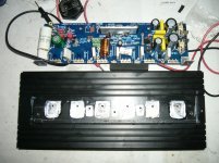
why have the big loops on the output resistors.see photos
These are aerials sending out interference.
Low Loop Area. everywhere.
I don't know where you are getting your information............. from what I'm aware the quality of components which we normally source from the retail electronics outlets may have lots of deviations in the parameters, wont these affect the performance of the amplifier? E.g. a 100 ohm resistor may be anywhere between 90-120 ohms, because solid state amplifiers use several components and if all of these components vary in their properties, how can we assure the output quality?..............
eg.
resistors:
10% 100r is from 90r to 110r
5% 100r is from 95r to 105r
1% 100r is from 99r to 101r
0.1% is from 99r9 to 100r1
1% metal film resistors are standard stock now and have been for at least two decades.
loops at resistors
why have the big loops on the output resistors.
These are aerials sending out interference.
Low Loop Area. everywhere.
As far as I can remember ( made this part 2 years ago ) These resistors are non-inductive power resistors ... so instead of a wire wound resistor there is only one big loop .... is it worse or better ? simply equivalent ?? ... Quite difficult to tell for me .....
Not sure that the emitter resistor extra loop area matters at the frequencies this amp is limited to passing. I've built amps with non inductive and inductive emitter/source resistors. Maybe my sources and speakers aren't up to snuff, but I can't hear the difference in a Leach amp.
There are other considerations besides EMI, too. Leaded power resistors are rated in free air. If they are mounted directly on the board they must be de-rated. Mounting them a little off the board gives them a bit better air circulation and they are able to handle a more power, although still not as much as free air.
Engineering is about compromises. There are often competing requirements, you have to make the choices that make the most sense to you and your priorities. If EMI is your biggest concern, then make it as close to all surface mount as possible and keep the output transistors close together. Of course that makes getting rid of the heat more difficult...
The resistor does not have to be close to the PCB. Standing up is good for air circulation, Upstanding does create a temperature differential. In precision work that temp diff causes problems. As an output resistor, the temp diff is not a problem.
The loop is the problem.
The Flow Route through the resistor body should be close coupled to the Return route via that exposed wire.
Fold the Return wire close to the body of the resistor. That small loop area makes it less inductive and less of a transmitter.
The loop is the problem.
The Flow Route through the resistor body should be close coupled to the Return route via that exposed wire.
Fold the Return wire close to the body of the resistor. That small loop area makes it less inductive and less of a transmitter.
Thanks for you comments. Fuses burned and the resistors caught fire, the mains fuse did not burn. I checked mica washers, perfect condition, drivers tested, good, no leakage, bias transistor perfect. Three surviving MGs are good and have exactly the same Hfe as before.
This module was the first I built two weeks ago so I was switching it on and off a number of times to see how it behaves before I built the second unit which is a touch different. It has 120 ohm between driver emitters, has 560 ohm instead of 680 i bias circuit as recommended by os as I use matched 2sa1430/c5171 as drivers rather than mje15xxxs.
So the puzzle is unsolved. Either short or massive sudden oscillation.
cheers,
I can think of one more issue that caused that symptom for me in the past. It is hard to check now, but is it possible that one of the outputs didn't get good contact with the heatsink? On my Dx MKIII, I had loose fitted the outputs as I was mounting everything and then went back and snugged everything tight. Unfortunately, one of the outputs didn't get snugged tight. All looked fine until I raised the bias and then after a short while it blew the fuse. When checking things out I read a short on that side of the output bank. I discovered the issue while removing the cinch screws from the outputs. The thermal paste was noticeably less compressed on that one output. Anyway, it is possible that what you had was thermal run-a-way and not oscillation.
Just something to look for.
Blessings, Terry
I have noticed this unequal temperature on the heatsink mounted devices, on a Roender 3pr.
I ran out of pink insulators, I had 5 left. The sixth device got a mica insulator.
the first thing I noticed was that the Ic were not the same.
On rechecking I realised that the mica mounted transistor was running cooler than the others.
The very good, but not Keratherm, insulators were allowing the device Rth c-s to increase, slightly. The Ic increase was significant.
Had I used 5 Keratherm and 1 pink and not checked actual currents, then Thermal runaway may have become a problem.
Changed to all mica.
Last edited:
Thanks stili4given,
That would be nice if it was a case of poorly tightened transistors. I think they were well tightened but there is a slight chance that one or two were not perfectly tightened and actually only two burned not 3 as I thought before.
I'll post a picture of the heatsink with mica washers still on it when I get back home from work. Two of these micas have more paste under them than the other so they were somewhat less tightened. Nevertheless, would that be enough to burn a transistor at only 60mA fed to it?
But I had a loose bolt on Q10 (VAS). This bolt somehow got loose but that was well before I soldered in power transistors. I noticed that when powering up for an initial testing. Luckily this transistor does not draw much current and probably could operate without a heastink. After 20 minutes testing its part of the heatsink is cooler. The other two VAS transistors (Q11 and 12) do all the heating as I have reduced R12 to 6.8k, R13 to 7.5k and and added 68uF to C5 so now it's 110uF on this board. The other board has nominal 100uF which in reality is 90uF.
cheers,
Last edited:
Pictures of my HB modules and of the burned one with heatsink andmica washers. Difficult to see clearly but two washers have more paste underneath than the other four. Maybe it's a clue but would these transistors burn with 60mA bias?
cheers,
PS what is the best bias controlling transistor?
cheers,
PS what is the best bias controlling transistor?
Attachments

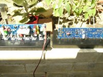
Looks like a bit of excess goop may have contributed. You want just enough to fill the surface irregularities but not so much to keep the mica from mostly contacting the heat sink. Goop conducts heat better than air, but not as well as mica. Use just enough goop to get a tiny bit of squeeze out around the edges. In the second picture the two end devices look like they almost squeezed out enough out, the others have significant excess. It may be the glare, though. The mica should look almost clear with no air bubbles under the contact area of the device.
I use a cotton swab, touch the goop in the tube lightly and wipe that little bit of goop on the surface of the device and heat sink side of the mica. You'll likely be surprised surprised to see how little goop is needed to get the surface fully covered.
I use a cotton swab, touch the goop in the tube lightly and wipe that little bit of goop on the surface of the device and heat sink side of the mica. You'll likely be surprised surprised to see how little goop is needed to get the surface fully covered.
Looks like a bit of excess goop may have contributed. You want just enough to fill the surface irregularities but not so much to keep the mica from mostly contacting the heat sink. Goop conducts heat better than air, but not as well as mica. Use just enough goop to get a tiny bit of squeeze out around the edges. In the second picture the two end devices look like they almost squeezed out enough out, the others have significant excess. It may be the glare, though. The mica should look almost clear with no air bubbles under the contact area of the device.
I use a cotton swab, touch the goop in the tube lightly and wipe that little bit of goop on the surface of the device and heat sink side of the mica. You'll likely be surprised surprised to see how little goop is needed to get the surface fully covered.
I built tens of PAs and this is the first time I got output transistors burned. True, almost my all bjts had V-I limiters, the other were lateral mosfets or verticals. I do not know why os dis not incorporate in HB any V-I limiter. With a speaker protection unit V-I liniter is not likely to damage any tweeter, besides V-I limiters are mostly needed as a protection against incidental shortening (that happened to me many times) but output shortening happens without speakers connected.
OK, point taken. So it looks that I applied too much paste and did not squeeze out enough of it but would 60mA kill MG6311/9411 even without a heat sink?
cheers,
Last edited:
At 60 mA and 60V rails you've got less than a watt - even a TO-220 device should handle that much power without a heat sink.
It could be oscillation or some other cause of high current. I had an open in the Vbe multiplier circuit of one of my Leach amps and it drove the outputs to high current as expected . Perhaps there was an issue with your bias transistor circuit - heat causing a solder joint to open up or similar.
It could be oscillation or some other cause of high current. I had an open in the Vbe multiplier circuit of one of my Leach amps and it drove the outputs to high current as expected . Perhaps there was an issue with your bias transistor circuit - heat causing a solder joint to open up or similar.
Soldering was perfect and neither the bias control transistor nor drivers were damaged. I inspected the board a few times since then. Nothing caught my eye. My first thought was: "oscillation" so I also checked drivers and their mica caps and desoldered these as well but they were OK.
So it looks that it was some sudden oscillation burst or some other cause as the amp behaved very well for quite a long time when it was plugged in in series with the globe. Globe would start to glow if something was happening but it did not. It was almost black and STABLE each time. So there was no oscillation then and there was no signal applied, which could trigger oscillation when it happened. If it was oscillation some part within the amp had to trigger it but which one?
V-I limiter would prevent burning of the output transistors but still there is the same question: what caused it? Oscillation or something else?
cheers,
Hi Janusz,
I'm certainly no expert, far from it. I do seem to have a knack for stressing things though. 😱 One other thing I have had happen that caused the bias to skyrocket was a loose driver. The driver overheated and the bias shot up almost instantly. With a light bulb connected not so much a problem but without
 Hope you find it.
Blessings, Terry
I'm certainly no expert, far from it. I do seem to have a knack for stressing things though. 😱 One other thing I have had happen that caused the bias to skyrocket was a loose driver. The driver overheated and the bias shot up almost instantly. With a light bulb connected not so much a problem but without
Hope you find it.Blessings, Terry
if you used silicon pads, you won't have to use grease...
i used kapton tapes on my latest build though....
i used kapton tapes on my latest build though....
Hi Janusz,
I'm certainly no expert, far from it. I do seem to have a knack for stressing things though. 😱 One other thing I have had happen that caused the bias to skyrocket was a loose driver. The driver overheated and the bias shot up almost instantly. With a light bulb connected not so much a problem but without
Blessings, Terry
Well, unfortunately or fortunately drivers were well bolted to the heatsink and survived without a scrach. On one hand I'm quite happy that it happened as it gives food for thought and if this puzzle is solved then something will be learned.
So the question is: what may cause some power transistors to burn without drivers and bias transistor being damaged???
cheers,
one reason is if you got fakes...
i have lots of cases repairing Sansui G-series amps wherein the output trannies fried and the drivers still live,
only the associated resistors got burned out, some resistors did not even show signs of burning, they were flameproof...
i have lots of cases repairing Sansui G-series amps wherein the output trannies fried and the drivers still live,
only the associated resistors got burned out, some resistors did not even show signs of burning, they were flameproof...
- Home
- Amplifiers
- Solid State
- diyAB Amp The "Honey Badger" build thread