Updated IPS. TPC and VAS
Hi Guys,
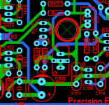
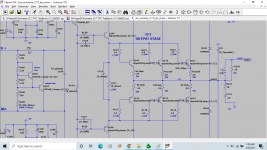
I have created a V2.7 of the Wolverine IPS board that has the TPC additions and the VAS buffer modifications.
I also updated Q12 to a BC550
The BOM and schematic will need review and re-numbering after a review.
P.S. I should become a magician getting that all to fit. 🙂
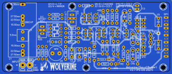
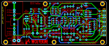
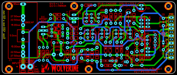
Hi Guys,
I have created a V2.7 of the Wolverine IPS board that has the TPC additions and the VAS buffer modifications.
I also updated Q12 to a BC550
The BOM and schematic will need review and re-numbering after a review.
P.S. I should become a magician getting that all to fit. 🙂
Attachments
Last edited:
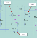
I think it would be prudent to consider more factors than just stability compensation, this doesn't seem like it has been properly vetted. Some compensation might be achieved by adding a base resistor to the Vbe multiplier transistor mounted on the driver heatsink and perhaps also the one mounted on the main heatsink. This in turn will probably affect the Vbe multiplier ripple compensation resistor as well.
We can add one (RCC2) to the base of Q104.
Is this what you were talking about?
Attachments
Hi Guys,
I have created a V2.7 of the Wolverine IPS board that has the TPC additions and the VAS buffer modifications.
I also updated Q12 to a BC550
The BOM and schematic will need review and re-numbering after a review.
P.S. I should become a magician getting that all to fit. 🙂
That looks really good Stuart, I'm really happy you you got it all to fit.
I'm currently looking at the bias stability and the effects of the base resistors.
Jeremy
Just a update.
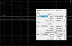
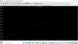
Jeremy and I worked on the sim last night and we have the distortion down to 0.00027%
100watts 8 ohm 20k
15 gain margin and 66 degrees phase margin.
That's without TPC
View attachment 957703
Jeremy and I worked on the sim last night and we have the distortion down to 0.00027%
100watts 8 ohm 20k
15 gain margin and 66 degrees phase margin.
That's without TPC
View attachment 957703
Last edited:
Image failed to attach.
I also want to add that this is a big step forward as the original circuit posted by OS under the same test condition had a THD of 0.073618%
I also want to add that this is a big step forward as the original circuit posted by OS under the same test condition had a THD of 0.073618%
Attachments
Last edited:
Image failed to attach.
I also want to add that this is a big step forward as the original circuit posted by OS under the same test condition had a THD of 0.073618%
Im not sure why. But This circuit should sim better than 0.073618% even close to mx power with simple 68pf miller capacitor.
Can you post original file that OS used.
Im not sure why. But This circuit should sim better than 0.073618% even close to mx power with simple 68pf miller capacitor.
Can you post original file that OS used.
Sorry my mistake, The I had been fiddling around with the DC offset and didn't realise it was way off. 0.001415% is the correct number based on OS original file.
All I have done is set the amplitude to 1.5v to match my testbench and the load to 8 ohms
Attachments
Hi Keantoken, I'm trying to finish off the PCB can you please comment on post #1142I think it would be prudent to consider more factors than just stability compensation, this doesn't seem like it has been properly vetted. Some compensation might be achieved by adding a base resistor to the Vbe multiplier transistor mounted on the driver heatsink and perhaps also the one mounted on the main heatsink. This in turn will probably affect the Vbe multiplier ripple compensation resistor as well.
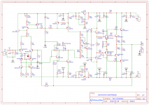
Unfortunately that schematic is outdated, not that it might not work but there are a number of improvements and we'll be posting an a new one soon.
Just wait a few more days. Hopefully by early next week it will all be finalised.Something I got lost in the variety of versions of Wolverine. Tell me, according to this scheme that I attached, everything will work in general, and then I already ordered the boards....
Improvements can be subjective. Some might be inaudible to most. I suppose the question is, will it work, reliably and with good sound quality.
Aspects like DC offset etc.
Aspects like DC offset etc.
Who knows, the amplifier is in the developmental stages and a prototype will build build and tested by people who are willing. The feedback from that will determine the next step. Either more simulation and testing or release to the DIYAUDIO store.Improvements can be subjective. Some might be inaudible to most. I suppose the question is, will it work, reliably and with good sound quality.
Aspects like DC offset etc.
More Thermal Sims
So here is a more realistic test for comparing 0ohms vs 100ohms for the driver base resistor.
Ambient is swept from 25°C to 40°C
Driver is 5°C above Ambient, Q103 thermally coupled to the Driver
Outputs are 15° above Ambient, Q104 thermally coupled to the Outputs
Below are plots showing bias current variation over temperature through one of the outputs emitter resistors
Jeremy
Attachments
Last edited:
I guess everything becomes an argument in audio. As for who knows. It's a blameless with additions. We can become pedantic, but we can also look at schematic and with relative confidence predict if it's going to have problems. Tweaking afterwards not excluded. He already made boards and is asking for advice, maybe just for peace of mind.
why are the second(q107) and third (q109) transistors the same at the output in the triple? Why isn't the second one 15032/33, for example, or of this type?
Hi Guys,
I have created a V2.7 of the Wolverine IPS board that has the TPC additions and the VAS buffer modifications.
I also updated Q12 to a BC550
The BOM and schematic will need review and re-numbering after a review.
P.S. I should become a magician getting that all to fit. 🙂
Hi Stuart
Did you verify the current on the LED's while the amp is clipping ?
It seems the current will be excessive .... Unless you use a huge value for R17... now you chose 27k .... did you verify the effect of such a high value resistor in the amp SR ?
In my build I found it affects SR if R17 is higher than 6k8
Last edited:
why are the second(q107) and third (q109) transistors the same at the output in the triple? Why isn't the second one 15032/33, for example, or of this type?
It doesn't need to be. OS chose to use those there from the Slewmaster builds, you probably don't need to go to an Output as a Driver until 4 or 5 pairs of Outputs.
- Home
- Amplifiers
- Solid State
- DIYA store "Wolverine" (Son of Badger) .... suggestions ??