Ok, thanks, what distortion numbers are you getting with a 8 ohm load at 20khz for a output power level of 100W RMS?I aimed for >60 degrees of phase margin, >15dB of gain margin with 20dB being even better, and gentle curves in the loopgain plot with no asymptotes, shelves, or sharp swings in phase -- not until far below unity loop gain anyway. There was no specific target for ULGF which came out to something like 850kHz for the circuit from #1041.
You're gonna make me do MATH ?! to figure out how many volts is 100W, got damn... 😉 ... I think it's +/-40V peaks.
(Can that be right? How is every amp with 45V rails not advertised as a 100W amp then? I probably need to repeat EE101.)
The TPC circuit from comment 1041 reports 0.001682% THD with 40V peaks.
The "baseline" TMC wolverine from comment 612 reports 0.001386% at same.
That's from the ".four" command the way ostripper sets it up -- with a 20kHz fundamental, adding up the ultrasonic distortion products. Looking at in-band distortion paints a similar picture -- the TMC amp produces moderately better distortion with moderately worse stability margins. Both circuits are well below 10ppm distortion in band.
You're gonna make me do MATH ?! to figure out how many volts is 100W, got damn... 😉 ... I think it's +/-40V peaks.
(Can that be right? How is every amp with 45V rails not advertised as a 100W amp then? I probably need to repeat EE101.)
The TPC circuit from comment 1041 reports 0.001682% THD with 40V peaks.
The "baseline" TMC wolverine from comment 612 reports 0.001386% at same.
That's from the ".four" command the way ostripper sets it up -- with a 20kHz fundamental, adding up the ultrasonic distortion products. Looking at in-band distortion paints a similar picture -- the TMC amp produces moderately better distortion with moderately worse stability margins. Both circuits are well below 10ppm distortion in band.
You need a minimum of 35-0-35 VAC 500VA transformer so you can get +/-45V rails under load for 100W into 8ohms (for two channels).
OEMs like to cheap out by using a higher secondary voltage and then under size the VA of the power transformer resulting in a saggy mess just to get the same +/-45V rails under load.
Last edited:
You're gonna make me do MATH ?! to figure out how many volts is 100W, got damn... 😉 ... I think it's +/-40V peaks.
(Can that be right? How is every amp with 45V rails not advertised as a 100W amp then? I probably need to repeat EE101.)
The TPC circuit from comment 1041 reports 0.001682% THD with 40V peaks.
The "baseline" TMC wolverine from comment 612 reports 0.001386% at same.
That's from the ".four" command the way ostripper sets it up -- with a 20kHz fundamental, adding up the ultrasonic distortion products. Looking at in-band distortion paints a similar picture -- the TMC amp produces moderately better distortion with moderately worse stability margins. Both circuits are well below 10ppm distortion in band.
Use the ltspice file from post #1067
It might help with that sort of thing as its all parameterised.
Voltage is Sqrt (P /R)
Your looking for about 28.28v
Leave the rails the same and just adjust the input voltage
Last edited:
Stuart,
I'm pretty good with ltspice do you want me to do some sims? I just need to know where the latest .asc file is. Post#1067? What do you want to see/concerned about?
I'm pretty good with ltspice do you want me to do some sims? I just need to know where the latest .asc file is. Post#1067? What do you want to see/concerned about?
I have been doing optimisation.Stuart,
I'm pretty good with ltspice do you want me to do some sims? I just need to know where the latest .asc file is. Post#1067? What do you want to see/concerned about?
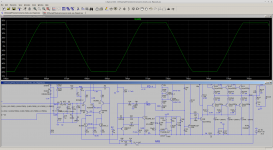
Here is my latest file. See if you can improve on it.
View attachment DIYAampEF3wolverine V2.6 TestBench V1.2.zip
I did notice that the DC offset control seams to be a bit finicky. Sometimes it causes the output voltage to latch at near rail voltage.
Not sure why its doing that.
Not sure why its doing that.
I did notice that the DC offset control seams to be a bit finicky. Sometimes it causes the output voltage to latch at near rail voltage.
Not sure why its doing that.
I noticed that too. I'm getting familiar with your test bench right now.
Setting the DC offset to close to zero seams to be a real pain. I usually do a sweep of Roff1 and let spice solve the value when vout equals zero. You look in the error log and there the value is. Plug it back into Roff1 and your set.I noticed that too. I'm getting familiar with your test bench right now.
But its not working as well as it used to on the HB circuit.
I end up just tweaking the value of Roff1 up and down 5 ohms at a time until the DC simulation solves quickly.
I haven't been able to get the control of the Vout as I usually do.
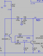
Hmm, the VAS Baker clamp diode contributes to simulated distortion, quite a few ppm.
It would be nice if we didn't have to trade off distortion and "civilized" clipping. The alternate Baker clamp below accomplishes that.
It works by letting the VAS buffer drive the (nonlinear) diode reverse leakage current, so the IPS doesn't have to. The 1k resistor connects at the base of Q13, not the emitter of Q12, so it can discharge the Cob of Q13 during slews.
We don't need a fancy super-low-leakage diode -- any old 1n4148 should do OK. The only downside that I see is it requires one extra diode.
Simulated distortion falls from about 16ppm to about 11ppm for a 100W / 20kHz test sinewave with this change.
We can reduce distortion further, as others mentioned, by reducing R17 to reduce the voltage it induces at the collector of Q12 (and whatever Early-effect current that exposes the IPS to.) I played with "flipping" the VAS buffer to a PNP, which removes the need for any current limiting, but it's more difficult to bias it and I was throwing too many extra parts in. So to heck with that. Anyway the distortion contribution of R17 seems to be pretty low.
Attachments
Last edited:
The only thing the Baker clamp does here is prevent Q12 from driving it's max current into the VAS base. It goes into the collector instead. However I don't see why the TTC004B would have any trouble handling that current with R17 set reasonably. Is there a need for a diode to begin with?
Dadod has a neat trick to deal with this. Requires 1 resistor only.
See slide 12
http://hifisonix.com/wordpress/wp-content/uploads/2019/02/Anti-Saturation-Diodes.pdf
See slide 12
http://hifisonix.com/wordpress/wp-content/uploads/2019/02/Anti-Saturation-Diodes.pdf
Last edited:
I thought the purpose of the Baker clamp was to prevent Q13 from saturating during clipping so that it can recover faster and not "stick" to the rail as much. That and reduced THD were my goals in redesigning it.
This question was the basis for the developing a better VAS in the Honey Badger thread:
diyAB Amp - The "Honey Badger"
If one studies the VAS design they could figure out how to apply the same principle for clipping here.
diyAB Amp - The "Honey Badger"
If one studies the VAS design they could figure out how to apply the same principle for clipping here.
Yep, that's the idea. When Q1 saturates, it's base current is drawn from it's emitter rather than increasing the VAS output voltage, averting positive feedback.
Also the BC capacitance is bootstrapped on the buffer transistor minimizing BC capacitance modulation.
Yes, as well as base modulation from Early effect, which can be a significant distortion from that transistor.
KT you're right, we don't need the diode. So what is the original Baker clamp diode doing? The amp clips fine without it. The VAS transistor saturates, and then no rail-sticking happens.
I guess the clamp reduces current at the VAS emitter during clip by a few mA, so you get just a few hundred mV more headroom. (Is that all?)
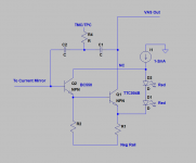
Here's an arrangement with the VAS buffer flipped around to PNP. It gives the same headroom as the original design with Baker clamp, but with less distortion (11ppm).
How this works: R20 raises the voltage at the buffer enough to keep its base in the region where the current mirror can drive it. D3 prevents the buffer's B-E junction from going reverse-biased during negative clip. C10 reduces distortion.
With the buffer flipped, R17 doesn't see a surge of several mA during clip, it conducts a constant 1.7mA.
I guess the clamp reduces current at the VAS emitter during clip by a few mA, so you get just a few hundred mV more headroom. (Is that all?)
Here's an arrangement with the VAS buffer flipped around to PNP. It gives the same headroom as the original design with Baker clamp, but with less distortion (11ppm).
How this works: R20 raises the voltage at the buffer enough to keep its base in the region where the current mirror can drive it. D3 prevents the buffer's B-E junction from going reverse-biased during negative clip. C10 reduces distortion.
With the buffer flipped, R17 doesn't see a surge of several mA during clip, it conducts a constant 1.7mA.
Attachments
- Home
- Amplifiers
- Solid State
- DIYA store "Wolverine" (Son of Badger) .... suggestions ??