jjs, thats a good one too.
I guess the "current source" could just be a 100k resistor to B+, no need to build yet another real current source.
I guess the "current source" could just be a 100k resistor to B+, no need to build yet another real current source.
A high voltage and high value resistor can approximate a current source so a resistor should be sufficient.
(60V-2*1.8V)/2mA=~27k (That is to ground)
(60V-2*1.8V)/2mA=~27k (That is to ground)
Last edited:
Yes, A 56k-100k resistor to the positive rail would be sufficient. The only down side of tying to the positive rail is that it becomes dissipation limited, 120V*2mA = .24W unless it goes to a 1/2W resistor.
Last edited:
Hi Guy's,
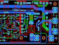
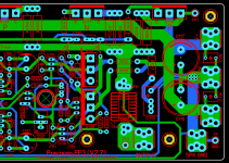
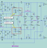
I added the parts to the EF3 board and did a creepage check.
That looks great Stuart. I'd like to change R128/129 to 100ohms and C118/119 to 470pF. This will be a little less lossy and works just as well. If there is 10mA of base current into Q107/Q108, R128/R129 at 120ohms will drop 1.2V vs 1V at 100ohms. If the base current is higher, well you get the picture.
Those RC networks really squash gain peaking tendency in the triple around 5-10MHz.
Jeremy
Hi Guy's,
I added the parts to the EF3 board and did a creepage check.
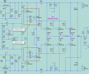
The PCB is wrong? R110 should be connected to Q105 E pole. It is not connected to Q107 B pole as in PCB.
Hi Guy's,
I added the parts to the EF3 board and did a creepage check.
Good catch, the bottom of R110 should be connected to Q108 base.
Hi Guy's,
I added the parts to the EF3 board and did a creepage check.
Awesome!
FWIW the 120R and 390p in the OPS isn't specific to TPC, it helps gain margin for TMC or plain old miller compensation equally.
Jpc2001,
Try post #1116
Holy heck. That gets the wolverine down to 6.5ppm of distortion for a 20kHz sinewave. The tallest distortion product is the 3rd harmonic but even that one is >106db down.
I wouldn't have guessed Early effect from the VAS buffer was contributing enough to show up -- even if you just ground its collector, that only brings distortion to 10ppm -- this is better.
Geez that's almost worth building another amp to try out. That's brilliant.
Thanks, I'll try and re route that.The PCB is wrong? R110 should be connected to Q105 E pole. It is not connected to Q107 B pole as in PCB.
I'll try and make these changes too over the weekend.Awesome!
FWIW the 120R and 390p in the OPS isn't specific to TPC, it helps gain margin for TMC or plain old miller compensation equally.
Holy heck. That gets the wolverine down to 6.5ppm of distortion for a 20kHz sinewave. The tallest distortion product is the 3rd harmonic but even that one is >106db down.
I wouldn't have guessed Early effect from the VAS buffer was contributing enough to show up -- even if you just ground its collector, that only brings distortion to 10ppm -- this is better.
Geez that's almost worth building another amp to try out. That's brilliant.

The PCB is wrong? R110 should be connected to Q105 E pole. It is not connected to Q107 B pole as in PCB.
Your correction is correct, mine is wrong on post#1129
The PCB is wrong? R110 should be connected to Q105 E pole. It is not connected to Q107 B pole as in PCB.
Updated, thanks again
Attachments
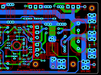
Those RCs may need to be different in the build if the simulation models aren't accurate, and if someone uses different transistors. Also the resistors are so large they will probably impact thermal compensation and may affect max output swing.
The resistors could be replaced with wire or low ohm resistor if you want. So it can be configured both ways. Bench tests will confirm the final config.
I was changing the R to 100ohm and the C to 470pF looks pretty much the same as 120ohm and 390pf. The R could maybe be reduced a little more with the appropriate C increase.
I was changing the R to 100ohm and the C to 470pF looks pretty much the same as 120ohm and 390pf. The R could maybe be reduced a little more with the appropriate C increase.
Last edited:
I think it would be prudent to consider more factors than just stability compensation, this doesn't seem like it has been properly vetted. Some compensation might be achieved by adding a base resistor to the Vbe multiplier transistor mounted on the driver heatsink and perhaps also the one mounted on the main heatsink. This in turn will probably affect the Vbe multiplier ripple compensation resistor as well.
Last edited:
Hi Guys,
there have been a number of good suggestions presented here.
We really need you to post schematics so they can be discussed and simulated BEFORE Stuart changes the PCB.
As you know, making changes to the PCB is very time consuming and nerve wrecking.
Thanks.
there have been a number of good suggestions presented here.
We really need you to post schematics so they can be discussed and simulated BEFORE Stuart changes the PCB.
As you know, making changes to the PCB is very time consuming and nerve wrecking.
Thanks.
Hi Guy's,Hi Guys,
there have been a number of good suggestions presented here.
We really need you to post schematics so they can be discussed and simulated BEFORE Stuart changes the PCB.
As you know, making changes to the PCB is very time consuming and nerve wrecking.
Thanks.
Harry has selected these parts as candidates for the RC network over the feedback resistor.
Mouser
C10 = RDE5C2A2R0C0P1H3B
R26 = 71-CMF501K0000FHEA
Considering the space I have, I think these are good options. I'm trying to minimise the amount of vertical space this takes up.

- Home
- Amplifiers
- Solid State
- DIYA store "Wolverine" (Son of Badger) .... suggestions ??