Should not "Rcc" be directly proportional in value to the difference between the Badger VAS I and this ?
OS
No, the value depends on type of OPS and Vbe multiplier other values.
I simulated both, VFA and CFA and good value for both is 75 ohm.
The value should be equal to the effective resistance of the Vbe multiplier. That changes with VAS current, but also trimmer position. So there is a bit of jank to it...
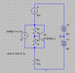
In simulation you can connect a sine current source across the Vbe multiplier to determine it's dynamic resistance and then see the invariance after adding the resistor.
In simulation you can connect a sine current source across the Vbe multiplier to determine it's dynamic resistance and then see the invariance after adding the resistor.
Show it.
Even as I did not do it in the slewmaster , I want to give accurate advice
in the build guide. Rcc is an offical component/option , it will be in the
BOM , as well.
OS
Even as I did not do it in the slewmaster , I want to give accurate advice
in the build guide. Rcc is an offical component/option , it will be in the
BOM , as well.
OS
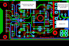
What if we put Rcc in the frontend module? We have to run an extra trace to the Vbe multiplier, but I think that would be fine.
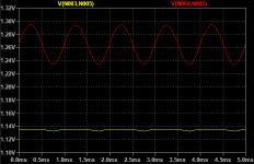
In this example the sine current source has 2mApp and the Vbe multiplier shows 60.4mVpp so the effective resistance is 30.2ohms.
Second picture shows bias voltage with and without the compensation resistor.
In this example the sine current source has 2mApp and the Vbe multiplier shows 60.4mVpp so the effective resistance is 30.2ohms.
Second picture shows bias voltage with and without the compensation resistor.
Attachments
Last edited:
The value should be equal to the effective resistance of the Vbe multiplier. That changes with VAS current, but also trimmer position. So there is a bit of jank to it...
In simulation you can connect a sine current source across the Vbe multiplier to determine it's dynamic resistance and then see the invariance after adding the resistor.
I simulated at VAS current 4 mA and bias of 90 mA for both VFA and symmetric CFA. For different bias(different trimmer position) it is not perfect but good enough.
Any plans of releasing the finalized PCB's on DIY audio store soon ?
Very helpful for pple like me.
Very helpful for pple like me.
Last edited:
Neater Route Option ?
Hi OS,
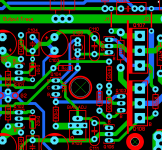
This maybe a neater route option. I'll e-mail you my file
Had to redo the Vbe , neater now with "Rcc" (Self resistor). Badger had
it. I can be an option. Safe !!
Should not "Rcc" be directly proportional in value to the difference between the Badger VAS I and this ?
OS
Hi OS,
This maybe a neater route option. I'll e-mail you my file
Attachments
What if we put Rcc in the frontend module? We have to run an extra trace to the Vbe multiplier, but I think that would be fine.
In this example the sine current source has 2mApp and the Vbe multiplier shows 60.4mVpp so the effective resistance is 30.2ohms.
Second picture shows bias voltage with and without the compensation resistor.
Another long trace ? nah.
Here is Rcc right on the Vbe decoupler (below). C109 is just a 2mm LS
electro. It does not need to be any special thing. I remember I just used
a 1uF 35V wima on my 5 OPS's . Might make ... yeah 2 + 2.5mm for the wima. (below) real tight Vbe now.
They are itching for this project .... let's get er' done !!
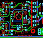
Stuarts aligned package with the Vbe update.
OS
Attachments
Hi OS,
This maybe a neater route option. I'll e-mail you my file
hell no ,sloppy 😀
I need PDF creators !!!!!!! I will have all the guides done today !!
OS
Last edited:

OS, you personally told me that, "it would be best to give the user the option to use a film cap for C109"Another long trace ? nah.
Here is Rcc right on the Vbe decoupler (below). C109 is just a 2mm LS
electro. It does not need to be any special thing. I remember I just used
a 1uF 35V wima on my 5 OPS's . Might make ... yeah 2 + 2.5mm for the wima. (below) real tight Vbe now.
They are itching for this project .... let's get er' done !!
Stuarts aligned package with the Vbe update.
OS
Were you currently have C109 that doesn't allow people to use a film cap.
Couldn't you move C110 to the left?
This would allow C109 to fit as it was before and give the user the option of using a film cap.
Last edited:
hell no ,sloppy 😀
I need PDF creators !!!!!!! I will have all the guides done today !!
OS
You also need alpha builders that can report on issue and construction details and make a real useful doc in the process. I am up for that if you make a small alpha run PCB set and sell it to me I got a blankets and I can send magic smoke signals. 😀
Pete
What about bypassing the input cap with a small mica ?
I had very good results with this technique when I need to use industrial caps in the input of my amps
What about bypassing the input cap with a small mica ?
I had very good results with this technique when I need to use industrial caps in the input of my amps
Film Option
Hi OS,
This may work.
Another long trace ? nah.
Here is Rcc right on the Vbe decoupler (below). C109 is just a 2mm LS
electro. It does not need to be any special thing. I remember I just used
a 1uF 35V wima on my 5 OPS's . Might make ... yeah 2 + 2.5mm for the wima. (below) real tight Vbe now.
They are itching for this project .... let's get er' done !!
Stuarts aligned package with the Vbe update.
OS
Hi OS,
This may work.
Attachments
What's with the rush for PCBs you guys???
Keantoken came along and made improvements. Dadod is now on board and has improved the design.
Take your time OS. Most of us don't want to see a "compromised" PCB after all the time that you have spent on design over the years.
Side note: I've always admired the way Luxman made their PCB for the amp you posted above. Copper buss bars on rails and output, regulated front end etc.
Also the PCB needs to be flexable for various componts that people want to use eg film caps.
When prototypes are made people like Jeff and Stuart have the equipment to test the amps for fine tuning.
That's my $0.02.
I have people over in the Badger thread saying I am betraying the enthusiast
because of -
-No VI limiters
-No onboard fuses
-Leaving these choices to the builder .... I'm bad and an idiot. 😡😡
My options ?
-$crew them and just go on.
-Design a full protection circuit for the store ??
I look on EBAY , protects , softstarts ... so many choices.
OS
because of -
-No VI limiters
-No onboard fuses
-Leaving these choices to the builder .... I'm bad and an idiot. 😡😡
My options ?
-$crew them and just go on.
-Design a full protection circuit for the store ??
I look on EBAY , protects , softstarts ... so many choices.
OS
I've always said any rail fuses belong at the supply. If they are going to be there they should be before the wire connecting the amp to protect from it shorting. Also nobody seems to be aware of what happens when one rail fuse blows. Not good without a DC detection system.
There are much better current protection options that VI limiting too.
There are much better current protection options that VI limiting too.
The HB didn't have VI limiting and everyone has got by.I have people over in the Badger thread saying I am betraying the enthusiast
because of -
-No VI limiters
-No onboard fuses
-Leaving these choices to the builder .... I'm bad and an idiot. 😡😡
My options ?
-$crew them and just go on.
-Design a full protection circuit for the store ??
I look on EBAY , protects , softstarts ... so many choices.
OS
I don't think that the fuses are a big deal. As its easy to add a inline fuse anywhere. Don't most power supplies have output rail fuses.
Besides. The PCB is not really big enough to add anymore comments.
Just adding that last resistor was a squeeze.
Don't stress about it OS.
We are trying to design a ppm distortion amplifier here. So let's keep our focus on that.
Last edited:
Some of the guys on the Badger thread are legends in their own minds. They contribute nothing and all they do is critise others who try to improve things.
I've yet to see them post in this thread. Too scared!
My take on fuses (which I hate) should be on the power supply board in case a wire falls off the amp PCB and touches the chassis. There are many options for protection. Jeff and X sell them, others are DIY, so why complain? I'm not saying that you shouldn't design your own but I'm sick of the negative comments by some members.
- Home
- Amplifiers
- Solid State
- DIYA store "Wolverine" (Son of Badger) .... suggestions ??