We originally started playing with the ESP32 as a front end for a preamp. Valery put together some really cool software that would start it up as a wifi access point. You would find it with your phone or tablet, then enter you actual wifi info and time zone through your phone. After a quick reboot it would be online and your phone became the remote control.
Nice.I forsee 23rd century bias control (below).
Kicad is nearly assimilated. Praise the Borg.
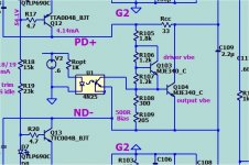
Default is passive. A BJT could bend this up to 1/3 A.
Sip 2 could not only be an idiot test point , but FB for SOA "violations".
Old 80's Genesis stealth had infrared class A bias control (2a per device.)
16A per channel bias ... heat the room up. 😱
I looked at N. Pass's video's. What a cool guy. He simplifies what he supports.
I like it. It's harder to do that with multistage AB design , I think I can do it.
A matching protection option will prOcede this. Because I I I I want it.
PS - I want the Schiit !!! pun intended ....
OS
If you plan on allowing a micro controller to manage these boards as an option.
Won't you want a sip connection point option (sip4) to control the DC offset as well?
We use opto-isolation for everything. There are audio grade digital pots available that could be used for auto-bias, but if this is as good as the Slewmasters were it's no really needed at all.
I have people over in the Badger thread saying I am betraying the enthusiast
because of -
-No VI limiters
-No onboard fuses
-Leaving these choices to the builder .... I'm bad and an idiot. 😡😡
My options ?
-$crew them and just go on.
-Design a full protection circuit for the store ??
I look on EBAY , protects , softstarts ... so many choices.
OS
Wow this language. Im not sure who called you bad, an idiot or mad, except yourself.
Let others have a difference of opinion on an open forum without feeling personally attacked. I'm not sure if your reaction like this is intended to silence those with deferent opinions than yours.
Picmicro is outdated and needs an external programmer. Something easy and cheap to get into these days are the ESP8266 and ESP32. If anyone is interested in making a protection circuit, Im sure some of us will help with the code and even a web interface if some fancy features are interesting.
Regards
I agree with you. External protection is the way to go. So that people can use what ever they want. It sure would be nice if the store had at least one option.I have people over in the Badger thread saying I am betraying the enthusiast
because of -
-No VI limiters
-No onboard fuses
-Leaving these choices to the builder .... I'm bad and an idiot. 😡😡
My options ?
-$crew them and just go on.
-Design a full protection circuit for the store ??
I look on EBAY , protects , softstarts ... so many choices.
OS
Nice.
If you plan on allowing a micro controller to manage these boards as an option.
Won't you want a sip connection point option (sip4) to control the DC offset as well?
Because DC offset is controlled in a custom way which is IPS dependant.
-Wolverine uses a small external DC "injection" at the blocking cap.
- Spook just offsets one of the CCS currents + a blocking cap.
-Hellraiser uses a servo to offset the Vf of the 2 LED CCS's.
-Other techniques are possible.
I re-thought SIP 3 , most of these high-end amps must have inferior
Vbe arrangements. Needing so long for warmup to stabilize is rediculous.
My Slews would immediatly stabilize. 70mA cold .... might drop to
65-68mA hot. Slightly negative co-efficient.
OS
We use opto-isolation for everything. There are audio grade digital pots available that could be used for auto-bias, but if this is as good as the Slewmasters were it's no really needed at all.
Might be better with Rcc. Just thought it would be a neat addition.
With a micro ,
-thermal overload could back off bias to a near class B state.
-the instant warmup scheme.
-"Audiophile" high bias AB (with a limit).
Since you use a lot of them -
-any recommends for a BJT one ?
-what do you do with the base .. let it float ?
-simulation shows a very low voltage to trigger the BJT. Infrared
LED ??
PS -SIP 2 can already serve as V/I and DC detect. Mouser 2 ended
female board to board connectors are common.
OS
Attachments
Wow this language. Im not sure who called you bad, an idiot or mad, except yourself.
Let others have a difference of opinion on an open forum without feeling personally attacked. I'm not sure if your reaction like this is intended to silence those with deferent opinions than yours.
Picmicro is outdated and needs an external programmer. Something easy and cheap to get into these days are the ESP8266 and ESP32. If anyone is interested in making a protection circuit, Im sure some of us will help with the code and even a web interface if some fancy features are interesting.
Regards
I might of over- reacted , but standard V/I limiters and fuses are so
"old school". I want more , not the same ol' .....
The offer for your help would be nice. Silence ?? I've been very open
to (most) of the "wishlists'.
We DO care .. here.
OS
I agree with you. External protection is the way to go. So that people can use what ever they want. It sure would be nice if the store had at least one option.
A simple universal one -
V/I , DC , softstart , and even SMPS control.
I would just use a 400W SMPS for a pair of these.
OS
I always use optos on switch mode as a digital input, usually HCPL2530 but I remember Valery mentioning a high linearity version that he used. I'll need to do some digging to find a part number. Yes the base is left floating. Preferred devices don't have a base connection to reduce the possibility of interference. CTR is the rough equivalent to transistor gain. One hurdle you will run into is the analog output of a microcontroller is PWM so it's not straight forward using it in an audio circuit. A digital pot might be a better option.Might be better with Rcc. Just thought it would be a neat addition.
With a micro ,
-thermal overload could back off bias to a near class B state.
-the instant warmup scheme.
-"Audiophile" high bias AB (with a limit).
Since you use a lot of them -
-any recommends for a BJT one ?
-what do you do with the base .. let it float ?
-simulation shows a very low voltage to trigger the BJT. Infrared
LED ??
PS -SIP 2 can already serve as V/I and DC detect. Mouser 2 ended
female board to board connectors are common.
OS
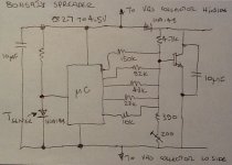
From Bonsai
That's pretty much digital stepped attenuator! I think I would want to isolate the microcontroller from that though. This might actually be the best solution, no need for infinite adjustment to back off bias for cooling, stepped adjustment would work.
Last edited:
I posted this concern a while back and no one responded, so I'll bring it back up one last time. Basically it's about Q107 & Q108 positioning.
On page 76 post #757 shows a picture what I'm getting at.
DIYA store "Wolverine" (Son of Badger) .... suggestions ??
Disregard if you don't think it's a problem
On page 76 post #757 shows a picture what I'm getting at.
DIYA store "Wolverine" (Son of Badger) .... suggestions ??
Disregard if you don't think it's a problem
Why not just step it externally.
What DAC could not provide 4-5 simple voltage steps between (0) 1-4V ??
Ropt at 15K limits the steps max deviation.
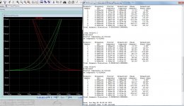
Thermally simulating Q103/104 shows normal co-efficient regardless
of step. Bonsai must of done this before the micro age.
OS
What DAC could not provide 4-5 simple voltage steps between (0) 1-4V ??
Ropt at 15K limits the steps max deviation.
Thermally simulating Q103/104 shows normal co-efficient regardless
of step. Bonsai must of done this before the micro age.
OS
Attachments
"Bonsai must of done this before the micro age."
😀
The idea behind the circuit is that you use a standard Vbe spreader (they generally work well, but only over a limited range!) to provide 1st order compensation, and you then use the controller to trim the spreader so it works over the full expected temp range. You would have to go through a calibration cycle, but these things are easy to do in software.
Original meanderings here:-
Some Ideas on Temperature Compensation for Audio Amplifier EF Triples
Very nice thread BTW - I've been lurking a lot - some good stuff here!
🙂
I posted this concern a while back and no one responded, so I'll bring it back up one last time. Basically it's about Q107 & Q108 positioning.
On page 76 post #757 shows a picture what I'm getting at.
DIYA store "Wolverine" (Son of Badger) .... suggestions ??
Disregard if you don't think it's a problem
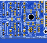
Both the Sanken 2sa1186 and ON njw0302 holes will sit @ 17mm H with full
insertion. A mje340 is a full 22mm from hole to lead end. No issue here.
Width , the Sanken is a little fatter at 2mm (lead to back) , MJE340 is 1mm
lead to back. ON 0302 is 1.7mm.
We only need 2.7 - 3.2mm max between leads. We have 6.6mm V2.42.
insulator + HS can be 3.4mm . standard 1/8" AL plate is 3.2mm perfect.
The M3 would be about 10mm long to screw the MJE and the NJW together.
MJE + sanken might need a 12mm M3.
OS
"Bonsai must of done this before the micro age."
😀
The idea behind the circuit is that you use a standard Vbe spreader (they generally work well, but only over a limited range!) to provide 1st order compensation, and you then use the controller to trim the spreader so it works over the full expected temp range. You would have to go through a calibration cycle, but these things are easy to do in software.
Original meanderings here:-
Some Ideas on Temperature Compensation for Audio Amplifier EF Triples
Very nice thread BTW - I've been lurking a lot - some good stuff here!
🙂
Thank you , your threads and the CFA stuff got me going.
I chose the $.88 HCPL-817 , just a modern faster 4N25. SMD-DIP-4 .. oh
no !!! Will they freak ? 😀
OS
Attachments
- Home
- Amplifiers
- Solid State
- DIYA store "Wolverine" (Son of Badger) .... suggestions ??