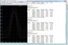
Pretty linear ... every .8V gives just about exactly 40mA more bias.
0V defaults to the trimmer.
2.2V gives the first 40mA step because the 1.4Vf of the diode. Looks like
a good future option for the OPS. Imagine programming just a few user
steps ( toggled by wi-fi ??).
OS
0V defaults to the trimmer.
2.2V gives the first 40mA step because the 1.4Vf of the diode. Looks like
a good future option for the OPS. Imagine programming just a few user
steps ( toggled by wi-fi ??).
OS
It could be a cool option! If it's going to be stepped a simple port expander could easily control it. Would we need to worry about thermal compensation for the optocoupler? It would suck to have it suffer thermal runaway!
It could be a cool option! If it's going to be stepped a simple port expander could easily control it. Would we need to worry about thermal compensation for the optocoupler? It would suck to have it suffer thermal runaway!
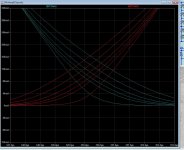
Just like in the Spooky the LED's have a neg. T opposed to the trannies
positive one. red and IR's just about negate the transistor.
I always strive for a slight neg. Tc on any design. (safe).
Actually the curve is a hump. This means high ambient for the opto will
back off on the boosted bias (negative Tc).
Current Transfer Ratio (CTR) and Response Time of Photocouplers / Optocouplers | Renesas
https://www.vishay.com/docs/48034/edn0715.pdf
Vishay agrees.
PS , this does not hold true for other linear opto's (triacs). Some BJT opto's have a Tc compensated driver. but ,
these need a separate supply.
OS
Last edited:
How many steps do you want? MCP23008 is 8 bit (256 steps) and a great device. MCP32017 is a pair of them in 1 box.
Last edited:
An IR remote and all 255 steps.. That would be a lot of resistors.
For my 3-4 steps and default , and assuming 5V at the MCP23008 pins.
39k = 150mA
47k = 125mA
56K= 100mA
68K = 80mA
no led R = default 40mA
OS
For my 3-4 steps and default , and assuming 5V at the MCP23008 pins.
39k = 150mA
47k = 125mA
56K= 100mA
68K = 80mA
no led R = default 40mA
OS
Last edited:
Actually it would only be eight resistors, but I'd let you figure out the math on it! For a linear scale second resistor would be double the value of the first, third resistor double the second...
How many mA are you planning to drive the opto with? It's only good for 20mA/IO but add a ULN2803 after it and you can run 40V 500mA.
How many mA are you planning to drive the opto with? It's only good for 20mA/IO but add a ULN2803 after it and you can run 40V 500mA.
For those values a 68k, 150k and 330k resistors would get you close. That would be a 3 bit circuit. We actually write a binary value to the expander so it's easier to work with the whole circuit operating in binary.
Actually it would only be eight resistors, but I'd let you figure out the math on it! For a linear scale second resistor would be double the value of the first, third resistor double the second...
How many mA are you planning to drive the opto with? It's only good for 20mA/IO but add a ULN2803 after it and you can run 40V 500mA.
The opto BJT shunts 60-120uA and the LED uses 70-140uA.
Very sensitive , Q104 still shunts 80% of the Vbe.
OS
The LED is barely turning on then. The math is pretty whacky due to the forward voltage of the LED but it looks like 75k, 100k, 220k and 470k would get you 8 steps in the range you want. All 4 in parallel would give you 33k3. No standard resistors seem to work out well with 68k as the base.
That IR is 1/1000th luminosity. But the photoBJT must be sensitive.
Consider that just 20R on the trimmer and a mV or two on Q104's base gets you
that 20-200mA bias range.
PS - is nothing also one of the steps ?
OS
Consider that just 20R on the trimmer and a mV or two on Q104's base gets you
that 20-200mA bias range.
PS - is nothing also one of the steps ?
OS
There's actually 9 possibilities in 4 bit. Write 0 to it and all is off. Write 8 to it and pin 0-3 are all on.
Are you going to make us solder an SMD MCU chip to get all these analog and digital ports needed for all the feature proposed, or could we settle on a DIP-28 or DIP-32 solution? I build a ham radio kit that was all SMD - it was a s**tshow. I eventually got it to work, but had to desolder a part and get a whole new replacement... This was the Peaberry SDR kit.
The first time you try to solder SMD parts of that pitch by hand, you will fail. I did. 0.1" please.
The first time you try to solder SMD parts of that pitch by hand, you will fail. I did. 0.1" please.
Do SMD the easy way, use a stencil and a toaster oven! I much prefer it to through hole. The expander is still available in dip18. It can be run from anything, an Arduino or ESP board would be the simplest options.
There's actually 9 possibilities in 4 bit. Write 0 to it and all is off. Write 8 to it and pin 0-3 are all on.
So , default (40mA) 0 and 8 15mA steps to 160mA (33k).
No SMD on Wolverine until you miss out on all the FUN !! That opto is
half as big as a 8 pin through - hole DIP.
On my SMD IPS , I opted for the biggest SOT packages , as well.
OS
I'll rework the math when I'm not falling asleep but it should be close if the opto is fairly linear. In my experience they have a bit of a range in forward voltage between batches lately so some actual testing might be needed. I may have the pins backwards on the expander too, some are MSB so you would be writing pin 7 first instead of pin 0.
- Home
- Amplifiers
- Solid State
- DIYA store "Wolverine" (Son of Badger) .... suggestions ??