Literary "artist" ... or just a hack ??
Pretty easy to change my "pitchfork villager" forum style to a more professional
one. (below)
I stopped at "magic smoke" and laughed. 😉
Feedback , too simplified ?
I might even add an addendum
of acronyms for "non-fanatics".
I'm not a Cordell or Self , but this is just a build guide.
OS
Pretty easy to change my "pitchfork villager" forum style to a more professional
one. (below)
I stopped at "magic smoke" and laughed. 😉
Feedback , too simplified ?
I might even add an addendum
of acronyms for "non-fanatics".
I'm not a Cordell or Self , but this is just a build guide.
OS
Attachments
Last edited:
Attachments

On to "the build".
I'm stuck on "magic smoke" , learned that term 10 years ago right on this
forum.
I'm not sure to what level I should tailer "the build" to ?
"Run in isolation" is quite an advantage with this project.
I'm "skitterish" with a build , personally.
I tend to do strange things , even on this amp ... I would either take a
known IPS and build just to the driver stage , tack 2 47R's onto the output
rail and fire it up.
Step two , after adjusting to 3.5V at the drivers ... just populate one pair
of "my precious" (outputs).
I don't think most would do this ?? With this amp , no IPS - just 2 15K resistors
from V+/- to PD+/ND-. Would this be confusing ? but , no magic smoke.
My point is that I am not sure of what the casual builder's "level " is.
It's hard to go back 20 years ("magic smoke" days). 😀
"throw off those chains of reason , let your prison disappear" - N. Peart RIP.
OS
Attachments
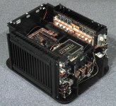
This casual builder started with 400V tube circuits, and then managed to build an 830V supply and chassis that been working over 15 years. No fires. No death. Fuses in key locations (center tap feeds) help. Grounding is key. But tube circuits are pretty forgiving in a special and neat way. You can badly misbias a tube - it might glow and angry orange - but it will still often work after you fix the problem and you can get on with the project. I Zero Biased an 845 by accident. It got very hot - the graphite plates went soft red. Those tubes are still in operation a decade late. The output transformer was unharmed. The transformer would have been an $700 mistake and it lived. That's not happening w/ SS....
Solid state - its very easy for things to die silently. You wont know what died unless you have test equipment and know what to measure. There is no red warning glow. Silicon junctions vaporize. If you are lucky you can feel heat coming off something. Screwdrivers shorting pins, grabber leads grabbing two pins, etc. I'd be less worried about destroying a $15.00 output transistor, then trying to find what it murdered on the board so I could desolder it and replace it.
I see alot of people getting lost and just replacing all the transistors on the board in their entirety hoping to get unlost/unstuck and getting it working...
When maybe just two parts needs to be swapped.
Last edited:
I agree to disagree here, no magic there just technic.
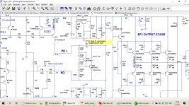
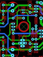
First of all I would not do layout in this way, it askes for to much compromisis.
Maybe you have some valid points but you will have to follow the discussion to see why we did what we did. As far as your feedback routing I addressed it here:
DIYA store "Wolverine" (Son of Badger) .... suggestions ??
CRT.
And the horizontal output tubes , got zapped by a 6JE6 and 6BK4 circuit.
Just 7 and playing in the back of a prototype RGB set in NY. (1968)
I quickly learned what a "damper" was. 25K from the CRT was a short "nip"
in comparison.
OS
And the horizontal output tubes , got zapped by a 6JE6 and 6BK4 circuit.
Just 7 and playing in the back of a prototype RGB set in NY. (1968)
I quickly learned what a "damper" was. 25K from the CRT was a short "nip"
in comparison.
OS
I've must of missed it in maybe the Slewmaster thread??? Why did name the Leach version "Spooky"?
I remember now , when I REALLY cranked it up all the way. Me and the others
listening got the "chills" , kind of spooky.
I could almost match this on the 3'rd amp pair I did , "CFA-X" , increased the
diamond buffer input stage regulator capacitors to 100uF. LF PSRR
seems to be tied to more presence in the bass. Same Hawksford VAS as Spook.
KT's NFB ground return might enhance a CFA's performance. Here , there
actually is current to consider. Helraiser = 150mA NFB @ 110V p-p.
PS - consider , with current ... the back EMF of the bass driver affects
the phase of NFB. Spook (VFA) might still be top dog.
OS
BUT: Having a particular design open to community discussion will always lead to "but you could" or "one never would" etc. from any more or less experienced member. Sure all this can be worthful, sure you can discuss how a single trace's width could improve THD by 0.1ppm... bla, I just think it's time for Pete to conclude and fix the design. It's modular, open to a variety of BOM part options and should go live now... am I wrong?
We should accept any feedback if it points to an obvious failure. Holding up everything for someone's opinions on what is a "wide enough" trace will open the door to all sorts of other similar hangups. If it is a problem, then it should be possible to show with math or simulation or experience or example.
I don't really like the long traces either, but I accept the reasoning for why they are like that.
From my experience, we will learn far more from the first build than we will if we bicker over the design until everyone is tired. It is better to fail while we still have some fight in us.
keantoken:
great suggestion - i like it!
"It is better to fail while we still have some fight in us."
great suggestion - i like it!
"It is better to fail while we still have some fight in us."
From my experience, we will learn far more from the first build than we will if we bicker over the design until everyone is tired. It is better to fail while we still have some fight in us.
You nailed it down 😀
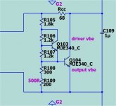
If not to late, I suggest to include so called current compensation resistor (D.Self) in this case it's R5. Without it bias current fluctuate greatly with change Of the VAS current(different reasons, thermal...)
I simulated it and 75R looks optimal.
I simulated it and 75R looks optimal.
Attachments
Vbe realities.
With a steady VAS I , never seen an issue.
2Q ccs's negate natively , so do LED based ones depending on Vf vs. temp.
That covers the Wolverine. I could not get a Wolverine CCS to change at all ,
even with hair dryer.
Spooky (symmetrical) , a little more sensitive. But , the LED CCS's were
negated by the LED hawksford.
I know this may sound crude , but I put the slewmaster on the snowbank.
Then I metered it before rocketing the temp with a hair dryer.
By doing this , I also determined the MJE340 for the Vbe's and ended up
with a slightly negative Coeff . at the upper end of my "hair dryering".
There is the trusty simulator (and my baseline HK680) , but actually cycling
the amp through that big a temperature range eased my mind.
I actually did this with all the slewmaster prototypes.
I could easily add your resistor ( or a option component) , I call it "Rcc".
Much space in the Vbe area.
OS
Probably with VFA where VAS current is controlled by CCS is not big problem, but with symmetrical CFA could be, better prevent then be sorry.
We should accept any feedback if it points to an obvious failure. Holding up everything for someone's opinions on what is a "wide enough" trace will open the door to all sorts of other similar hangups. If it is a problem, then it should be possible to show with math or simulation or experience or example.
I don't really like the long traces either, but I accept the reasoning for why they are like that.
From my experience, we will learn far more from the first build than we will if we bicker over the design until everyone is tired. It is better to fail while we still have some fight in us.
I agree on your major points. Except the "longer traces". It was a 10K Pass
amp that validated your NFB return advice for me. But how does he get away
with a 300mm + ribbon cable length for his NFB ?? I even have a couple
Darzeel schemas with separate OPS boards (also running NFB through a wire).
My last example was the hand crafted luxman ,
with the Japanese hammer guy pounding out 3 custom IE's for the supply per week.
This where I originally got the shielded cable idea (below 1). That is a BF-1000 $22K.
Both the Pass and the luxman are free to put the IPS's anywhere in the box.
The more high end designs I see , the attention to the loop is evident. But
not to it's length.
OS
Attachments
Last edited:
Probably with VFA where VAS current is controlled by CCS is not big problem, but with symmetrical CFA could be, better prevent then be sorry.
Your CFA experience guides me to add this "Rcc" option. I knew of the
Self resistor (Badger) , but decided to fine tune the IPS's for rock solid output.
Along with the snowbank to hairdryer testing , it worked.
This OPS could have a CFA plugged into it.
OS

Done
Had to redo the Vbe , neater now with "Rcc" (Self resistor). Badger had
it. I can be an option. Safe !!
Should not "Rcc" be directly proportional in value to the difference between the Badger VAS I and this ?
OS
Probably with VFA where VAS current is controlled by CCS is not big problem, but with symmetrical CFA could be, better prevent then be sorry.
Had to redo the Vbe , neater now with "Rcc" (Self resistor). Badger had
it. I can be an option. Safe !!
Should not "Rcc" be directly proportional in value to the difference between the Badger VAS I and this ?
OS
Attachments
Last edited:
- Home
- Amplifiers
- Solid State
- DIYA store "Wolverine" (Son of Badger) .... suggestions ??