Yes , I seen the blobs. This is better for an amp.I prefer to put the female connector on the board with the power supply. It's a little safer that way, no exposed high voltage pins. The two row jumper would work though.
Another option is a small solder blob jumper to activate/ deactivate a trace. I use them for address selection for I2C devices, but they work well for disconnecting supply regulators. ect in big SMT boards.
Safety !! yeah -
If they had the socket not connected , would they not have the power off ???
They would fry the amp / blow fuses.
The male on the main pcb is better. The females have limited insertion
lifetimes (I've been hitting the spec sheets).
I already made the change.(below).
If they complain about even getting a 3$ connector - jumper the SIP pads.
Ultimate perfect solution - no solder blobs , just a female bridged header
that could also be test points. .
Even those 2.54mm motherboard jumpers would work.
PS , maybe bridged traces under the board between the rows if no connector
available... as well. (solder blobs ?)
Edit - with the female header one could even tap the 4 regulators for devious tinkering.
OS
Attachments
Last edited:
I did not save it before I exported it to JPG.
I'm moving to NY soon. No parts for a while.
But thank you. Perhaps we could choose a willing tester that is not moving.
I'll be very close to Canada soon.
OS
I'm still here if you looking for a tester😉
Let them make fun of my through -hole.
Another level of perfection , check out that IPS/VAS (below).
It will preserve 2ppm , I think ...
I port this to my hawksford VAS in the SMD greenamp.
Layout style is not supported on autoroute. Autoroute
is 20 years in my brain. AI might get it someday , but not today.
OS
No one is mentioning auto router. Modern Cad does not equal auto router
I mentioned the female socket on the power side because it's standard practice for any connector, but it's not absolutely necessary by any means. The two row header would make things really slick for initial testing. We could go really lazy and make up a small plug in test board / header to run the input stage in isolation. I did this with the NS inputs.
Hi OS,Perhaps we could choose a willing tester
I'd be interested in testing one of these and providing feedback.
As you know I have all the test gear.
I have also recently ordered the Distortion Magnifier to go with my QA401 as my current HB build is measuring distortion at 0.00043% at 1K which is actually equivalent to the QA401's loopback distortion. So the actual distortion is unknown for now.
I could also accurately measure the loopgain so the phase and gain margins are know.
Let me know if you're interested.


I'm still here if you looking for a tester😉
You I must talk to ...
You did the spooky. It is said that it's performance changed depending on where
the ground or lifted ground was connected.
Please tell us.
This is the one design decision I have not finalized.
Thanks.
OS
Hi OS,
I'd be interested in testing one of these and providing feedback.
As you know I have all the test gear.
I have also recently ordered the Distortion Magnifier to go with my QA401 as my current HB build is measuring distortion at 0.00043% at 1K which is actually equivalent to the QA401's loopback distortion. So the actual distortion is unknown for now.
I could also accurately measure the loopgain so the phase and gain margins are know.
Let me know if you're interested.
View attachment 938300View attachment 938301View attachment 938302View attachment 938303View attachment 938304View attachment 938305View attachment 938306
Yes , sounds good.
With the "Anal level" I am aiming for in this update to the store amp , it would
be great to actually see if it works as good as it should.
This one is "Slewmaster" based.
Many forum members have helped and (tested) this group of designs.
The new store amp (Wolverine) is a way to redeem myself for my
amateurish attempt 6 years ago.
Many people helped with the Badger , but in reality it is one of my learning
designs that I was drawing with a Sharpie on FR4 😱 .
I want this one to "wipe the floor" compared to ANY project offered in the
current store .... So any tester is welcome.
Since it has modular capabilities - there will even be more (testing).
The Wolverine could let you listen to a 1980's Nikko integrated amp with
the simple plugging in of a daughtercard.
The only level this one has not reached is the non-switching OPS. Basing
the OPS on the HK680 amp is prudent. I own it , it is my re-capped garage amp
almost 32 years old and still sounding great. The oldest "Slewmaster" !!
OS
I mentioned the female socket on the power side because it's standard practice for any connector, but it's not absolutely necessary by any means. The two row header would make things really slick for initial testing. We could go really lazy and make up a small plug in test board / header to run the input stage in isolation. I did this with the NS inputs.
I was looking at what I could connect to a standard 2.54mm DI header.
So many board to cable options at Mouser.
It is what they use for CMOS bios resets and PC motherboard standard connectors. Seems 2.54mm is the most standard. 10k products - molex
and others - common.
Those tips I gave with the passive OPS biasing , and IPS local feedback
could be implemented on the right Female header configuration.
As I said , I did not copy the NS .... this would of been the end result if
the store wanted an update 3-4 years ago. I had something like this
originally envisioned while I was doing the slew.
I picked the Euro-terminals to avoid the "unobtainium" factor.
OS
.100" or 2.54mm have been the standard for at least half a century so they are the most popular. One bug I have with them is manufacturers will often stop producing them out of the blue after you've tailored a project to fit it. Molex seems to keep going though. An 11mm standoff works perfectly with theirs.
I love this. I'm no EE, so I don't have any useful input, other than I'm looking forward to the final design and I think it has the potential to be a very popular amp.
Subscribed!
Subscribed!
.100" or 2.54mm have been the standard for at least half a century so they are the most popular. One bug I have with them is manufacturers will often stop producing them out of the blue after you've tailored a project to fit it. Molex seems to keep going though. An 11mm standoff works perfectly with theirs.
Link that 11mm ... is it SIP/female? Do you use the 6 or 8 pin ?
I was thinking of sourcing a "board stacker" - https://www.mouser.com/ProductDetail/Samtec/DW-07-07-T-D-200?qs=0lQeLiL1qyaDOngxoEBenQ%3D%3D
to get my desired height.
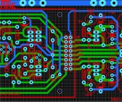
(Below) is the current 4'th final ... haha ! PCB.
I was thinking that one could have the onboard wolverine fully populated ,
have enough clearance to just plug in a Spooky or whatever right on top.
Either a standalone project (wolverine) with modular capability OR just
a OPS/regulator "devious playground" for IPS's.
OS
Attachments
I love this. I'm no EE, so I don't have any useful input, other than I'm looking forward to the final design and I think it has the potential to be a very popular amp.
Subscribed!
I'm no EE ... either , just an Fanatic/perfectionist. 😀
OS
I was thinking that one could have the onboard wolverine fully populated ,
have enough clearance to just plug in a Spooky or whatever right on top.
Either a standalone project (wolverine) with modular capability OR just
a OPS/regulator "devious playground" for IPS's.
OS
This would be slick. 🙂
other implementation
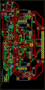
Hi OS and the others:
I am closely following the progress of this project. I had a similar idea for the Slewmaster Amp. I have attached my current state of the boards to you. My Slewmaster board also has OP transistors in line, is 170 * 85mm in size, could be mounted on the heat sink at right angles or in parallel.
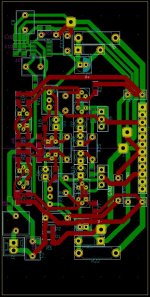
The IPS (Greenamp VFA and Kypton-ND) are each 100mm * 50mm in size, are connected to the Slewmaster at right angles via connectors and use a mix of SMD and THT components.
At the moment I'm not quite finished, but if you are interested, I can share the drafts. I also use the open source SW KiKad🙂.
Now to my questions:
1. There were changes in the dimensioning of the Slewmaster resistors. What was the reason for the changes?
2. The Greenamp-CFA (https://www.diyaudio.com/forums/solid-state/369758-diya-store-wolverine-son-badger-suggestions-11.html#post6588859) is quite different from the Kypton-ND (different servo input and one less transistor in the VAS). Does this IPS reach the Kypton-ND performance?
Hi OS and the others:
I am closely following the progress of this project. I had a similar idea for the Slewmaster Amp. I have attached my current state of the boards to you. My Slewmaster board also has OP transistors in line, is 170 * 85mm in size, could be mounted on the heat sink at right angles or in parallel.
The IPS (Greenamp VFA and Kypton-ND) are each 100mm * 50mm in size, are connected to the Slewmaster at right angles via connectors and use a mix of SMD and THT components.
At the moment I'm not quite finished, but if you are interested, I can share the drafts. I also use the open source SW KiKad🙂.
Now to my questions:
1. There were changes in the dimensioning of the Slewmaster resistors. What was the reason for the changes?
2. The Greenamp-CFA (https://www.diyaudio.com/forums/solid-state/369758-diya-store-wolverine-son-badger-suggestions-11.html#post6588859) is quite different from the Kypton-ND (different servo input and one less transistor in the VAS). Does this IPS reach the Kypton-ND performance?
Attachments

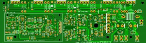
The project that keeps on giving.....
This was my sales pitch to management.
I also had them read the Slewmaster thread. They liked the content.
Looking at the current store projects.... I won't comment. 🙄
SMD option , modular .... I think it should be Forum standard.
Just think of it - I have almost EVERY amp EVER designed on this forum AND
at least .... hmmm ... 67 classic Japanese 20th century designs ported
to this EF3 OPS.
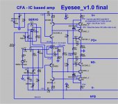
Plus op-amp (EyeSee-below) IPS's ... truly unique. Several more unique ones,
as well.
I have about 140 LT simulations total.
OS
This was my sales pitch to management.
I also had them read the Slewmaster thread. They liked the content.
Looking at the current store projects.... I won't comment. 🙄
SMD option , modular .... I think it should be Forum standard.
Just think of it - I have almost EVERY amp EVER designed on this forum AND
at least .... hmmm ... 67 classic Japanese 20th century designs ported
to this EF3 OPS.
Plus op-amp (EyeSee-below) IPS's ... truly unique. Several more unique ones,
as well.
I have about 140 LT simulations total.
OS
Attachments
Last edited:
Hi OS and the others:
I am closely following the progress of this project. I had a similar idea for the Slewmaster Amp. I have attached my current state of the boards to you. My Slewmaster board also has OP transistors in line, is 170 * 85mm in size, could be mounted on the heat sink at right angles or in parallel.
The IPS (Greenamp VFA and Kypton-ND) are each 100mm * 50mm in size, are connected to the Slewmaster at right angles via connectors and use a mix of SMD and THT components.
At the moment I'm not quite finished, but if you are interested, I can share the drafts. I also use the open source SW KiKad🙂.
Now to my questions:
1. There were changes in the dimensioning of the Slewmaster resistors. What was the reason for the changes?
2. The Greenamp-CFA (https://www.diyaudio.com/forums/solid-state/369758-diya-store-wolverine-son-badger-suggestions-11.html#post6588859) is quite different from the Kypton-ND (different servo input and one less transistor in the VAS). Does this IPS reach the Kypton-ND performance?
If you could standardize your IPS's to this amp's 8 pin
(ND/12v/V+/PD+/GND/ND-/V-/-12) scheme , you might have a wide audience in the end.
The "Greenamp" is the simplified Kypton-ND with just a standard Hawksford
cascode. Clips better than the super-pair ND.
Having the cap multipliers feeding the simple series zener regulators is better
by far than the hot,dirty standalone zeners in the ND.
Positive servo FB in the greenamp - offset is microvolts instead of millivolts.
Diamond pair and current feedback pair would be ideal as dual matched SMD
SOT-23-6 packages.
10ppm - 20k/4R with good clip and 110db psrr. Close to the wolverine with 4X
the slewrate. Simple and easily ported to both SMD and this project.
Edit - the resistors give the choice of either ceramics like the KOA BPR55-56 series
or dual standard 15mm 2W .47R in parallel. Either group can be had in wirewound or metal film versions.
OS
Last edited:
Here's an 8 pin Molex female connector. https://www.mouser.ca/ProductDetail/Molex/90147-1208?qs=QESXi79X%2BKr2ZspN0c66Rg== It's connector portion is 8.5mm tall. The 16 pin male header to match would be https://www.mouser.ca/ProductDetail/Molex/90131-0928?qs=kEwmkoUtv7QhuSNbPKtflg== with a 2.5mm spacer. These seem to be standard dimensions for most of the Molex line so you can pick and choose plating, ect.
That adjustable mezzanine connector looks neat! Is it meant to plug in or solder both ends?
Adafruit sells a header kit for the Arduinos that would work here too. I think there's an 8 pin one in the kit. https://www.mouser.ca/ProductDetail/Adafruit/3883?qs=/ha2pyFaduidPXPXSuFTA%2B17jDyV9poj5YQY8EXFvtY=
Adafruit sells a header kit for the Arduinos that would work here too. I think there's an 8 pin one in the kit. https://www.mouser.ca/ProductDetail/Adafruit/3883?qs=/ha2pyFaduidPXPXSuFTA%2B17jDyV9poj5YQY8EXFvtY=
- Home
- Amplifiers
- Solid State
- DIYA store "Wolverine" (Son of Badger) .... suggestions ??