Just wanted to share some information regarding dual mono implementation I came across in the Ultimate NOS TDA1541A thread during my research.
Building the ultimate NOS DAC using TDA1541A
John from ECDesigns was discussing testing of an I2S splitter with the 1543 (amongst other things that are over my head).
Someone asked a question regarding the use of two TDA1541A in his DAC.
John replies in post 5007 regarding dual/mono use of the 1541A.
Other questions follow and John goes on to explain benefits of using the 1541A in a dual/mono configuration.
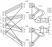
One bit of information it appears to hinge on (to my understanding) is that you are supposed to be using the stereo DACs embedded in a single TDA1541A chip which are closely matched to produce the signal for one channel (left or right) on the output.
He explains how this combats issues with jitter induced by using them in parallel amongst other things.
That to me implies that you need to feed both left or both right channel signals from your splitter (in our case the I2StoSim) to the inputs on a single D3 board (disregarding left and right input labeling) which would allow its TDA1541A to process only left or right channel data?
Building the ultimate NOS DAC using TDA1541A
John from ECDesigns was discussing testing of an I2S splitter with the 1543 (amongst other things that are over my head).
Someone asked a question regarding the use of two TDA1541A in his DAC.
John replies in post 5007 regarding dual/mono use of the 1541A.
Other questions follow and John goes on to explain benefits of using the 1541A in a dual/mono configuration.
One bit of information it appears to hinge on (to my understanding) is that you are supposed to be using the stereo DACs embedded in a single TDA1541A chip which are closely matched to produce the signal for one channel (left or right) on the output.
He explains how this combats issues with jitter induced by using them in parallel amongst other things.
That to me implies that you need to feed both left or both right channel signals from your splitter (in our case the I2StoSim) to the inputs on a single D3 board (disregarding left and right input labeling) which would allow its TDA1541A to process only left or right channel data?
Hi Ryan
When connecting my rca chassis output wiring to each D3 board for either the right or left channel, what orientation should it be in regarding the two sets of output pads for each board? I have one pair of +/-wires for each rca output socket versus two pair +/- output pads on each D3 board.
If running dual mono just parallel the outputs to your RCAs
Will using two D3 boards in a dual mono configuration increase the current output for each channel and allow me to use lower value iv resistors to decrease distortion?
It will increase the current but it will not decrease distortion because the voltage will appear at both outputs. But you'll get a lower output impedance.
I hope the wiring can be clarified and understood. I think it's important to get the schemes illustrated here for end users not wanting to damage stuff. I've put a fair amount of time and money towards this and would hate to end up with unusable parts.
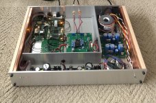
Here is how I have my 4 x D3 PCBs wired up with the I2StoSIM PCB.
2 x D3 PCBs only are required for balanced output but if you double up you have extra current to allow for a lower value load resistor resulting in less losses in the transformer and a lower output impedance - although I still needed a current buffer before my F5 amp.
Also, the way I have drawn the GNDs was for clarity, you should have the signal and ground wires twisted going to the transformer. The Primary and secondary GNDs should be connected as well as the transformer shielding can.
Attachments
Last edited:
That to me implies that you need to feed both left or both right channel signals from your splitter (in our case the I2StoSim) to the inputs on a single D3 board (disregarding left and right input labeling) which would allow its TDA1541A to process only left or right channel data?
This is what I mentioned in post #812
If using two D3 boards in a dual mono config I would recommend using one D3 board for the left channel and one for the right, you'll get better channel separation this way and it should sound better.
Balanced?
The wiring from the I2StoSIM to D3 is correct, just how you connected the analogue outputs is wrong, connecting the signal to the inverse signal will null the output. Instead these outputs need to be dealt with separately like I showed in post #824.
Last edited:
Yes...thank you very much Ryan.
Sorry it took me a couple times around for it to sink in.
As soon as I looked at Mark’s illustration again I realized he had come to the same conclusion already.
I’m so close, but still a little paranoid and sorting out how to fire up each power supply and board separately first to test for proper voltages prior to connecting my boards and afterwards confirming proper voltages at my chips.
I also need to figure out how to adjust the output resistor network to null any offset I think?
I’m wondering if that has to be done for each board separately before I parallel the output wires?
I also need to figure out how to adjust the output resistor network to null any offset I think?
I’m wondering if that has to be done for each board separately before I parallel the output wires?
No problem 🙂
Yes, adjust the outputs separately before you connect them together. Adjust with the IV resistor in place.
When testing the capmx board, just use a dummy load of about 200R, once you see the voltage about right connect it up to the D3 and check your voltage and adjust R4 and R5 if you need to. Watch the voltage over a few days as the line regulation usually varies depending on the time of day and day of the week. If you get an average in the high 26V or low 27V range your about on the money. If your concerned about CC1 getting too hot you could get an adhesive heatsink and stick it onto the copper fill area that is attached to CC1.
Last edited:
Finally!!!...It’s Alive!!
I stumbled a little trying to adjust the offset, but then realized that I needed to connect the input side of the D3 boards and everything went perfectly.
The CMx supplies are swinging between 25.5V and 26.5V as observed so far. Not sure if I want to try and nudge it up a little for the lower output supply yet or not. It is working and does swing up to low 26.xxV region.
They are wired up in dual/mono configuration.
Using only some parallel Caddock MK132 on the output as iv resistors creating a 110 Ohm load.
It really sounds wonderful. As sweet and natural as I remember my Rotel 855...even better.
It’s taken forever it seems for me to pull this together, but I am really happy with the results.
I am finally using the gain potential of my system. My DCB1 Hypnotize based preamp has Jensen iron on the outputs giving me about 6dB. I am turning my pots up to 50-75% to get ”satisfying...enthusiastic” levels.
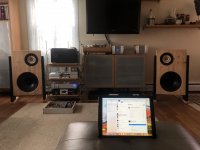
I am currently using my experimental open baffles as my horns were knocked over and damaged recently. The horn system is more efficient.
The sound is open with these baffles (LOL)...the stage not as restricted as the horns are more directional in my space which is a bit small for them. Just overall a natural analog like quality to the sound.
I am finally enjoying the work I’ve put into having a digital front end.
I stumbled a little trying to adjust the offset, but then realized that I needed to connect the input side of the D3 boards and everything went perfectly.
The CMx supplies are swinging between 25.5V and 26.5V as observed so far. Not sure if I want to try and nudge it up a little for the lower output supply yet or not. It is working and does swing up to low 26.xxV region.
They are wired up in dual/mono configuration.
Using only some parallel Caddock MK132 on the output as iv resistors creating a 110 Ohm load.
It really sounds wonderful. As sweet and natural as I remember my Rotel 855...even better.
It’s taken forever it seems for me to pull this together, but I am really happy with the results.
I am finally using the gain potential of my system. My DCB1 Hypnotize based preamp has Jensen iron on the outputs giving me about 6dB. I am turning my pots up to 50-75% to get ”satisfying...enthusiastic” levels.
I am currently using my experimental open baffles as my horns were knocked over and damaged recently. The horn system is more efficient.
The sound is open with these baffles (LOL)...the stage not as restricted as the horns are more directional in my space which is a bit small for them. Just overall a natural analog like quality to the sound.
I am finally enjoying the work I’ve put into having a digital front end.
Attachments
Last edited:
Finally!!!...It’s Alive!!
I stumbled a little trying to adjust the offset, but then realized that I needed to connect the input side of the D3 boards and everything went perfectly.
The CMx supplies are swinging between 25.5V and 26.5V as observed so far. Not sure if I want to try and nudge it up a little for the lower output supply yet or not. It is working and does swing up to low 26.xxV region.
They are wired up in dual/mono configuration.
Using only some parallel Caddock MK132 on the output as iv resistors creating a 110 Ohm load.
It really sounds wonderful. As sweet and natural as I remember my Rotel 855...even better.
It’s taken forever it seems for me to pull this together, but I am really happy with the results.
I am finally using the gain potential of my system. My DCB1 Hypnotize based preamp has Jensen iron on the outputs giving me about 6dB. I am turning my pots up to 50-75% to get ”satisfying...enthusiastic” levels.
I am currently using my experimental open baffles as my horns were knocked over and damaged recently. The horn system is more efficient.
The sound is open with these baffles (LOL)...the stage not as restricted as the horns are more directional in my space which is a bit small for them. Just overall a natural analog like quality to the sound.
I am finally enjoying the work I’ve put into having a digital front end.
Dear Chromenuts,
Congratulations, beautiful job! What are your perceptions about TDA1541 DAC sound? Is it a non oversampling mode?
Also, nice room setup! What are your speaker drivers in the baffles?
Rgds
Nilton
Thanks for the compliments.
@Nilton Yes the D3 is a non oversampling design. I have doubled up on D3 boards which allows me to run two TDA1541A in a dual/mono implementation (one per channel).
I am probably biased concerning the TDA1541A. The only piece of equipment I ever purchased new was a Rotel 855 with the TDA1541A. I lived with it and loved it for 20 years until it stopped working.
I don’t want to get carried away trying to quantify why I enjoy the sound of the TDA1541A except that I do.
I had tried to replace my old Rotel 855 with other players that were OK. I even got another used 855, unfortunately it was glitchy. I also own a SONY CDP-101 with the dual 1540 chips.
Eventually I got a used SMSL M8 and built a Shigaclone transport to try the Sabre chip everyone seemed crazy about. It was fine. I noted that it gave the impression of having more detail...but it didn’t have the natural analog like sound that I associate with the 1541.
250V is the maximum voltage for the tube. It is not necessarily the best operating voltage, or even a good operating voltage. The tube does not appear to behave in a very linear fashion at that voltage (i.e. will have high distortion).
Here is a data sheet with curves:
https://drtube.com/datasheets/6n2p-ev.pdf
My suggestion is to build it as designed. Lukasz Fikus knows a bit about about electronics.
Dear Ben Mah,
Just like Mr LinuxGeek, I saw some Lampizator projects, and he comments that 6N2P is the best tube for output stage on Satch DAC.
In the Mr Fikus PSU schematics, he uses only one rectifier, getting the 2nd output as a derivation from the first output. If I use dual mono configuration, wouldnt it be better to built a dual power supply with one transformer and one rectifier for each channel DAC?
Im starting to build a Hiraga Le Monstre Class A amp, and I will build a dual input choke power supply, with one trafo/rectifier for each amp board. So, to keep best channel separation, dual psu is a good idea for the DAC also?
And finally, if I will use tubes in the DAC I/V, why not build a tube rectifier also? In this case, a 5U4G tube rectifier works at 550v but DC voltage drops to aprox 440V due choke input filter, so could I to derive other voltages, like 150V to 6N2P and +5V, -5V and -15V to DAC inputs?
Tks and Rgds
Nilton
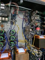
You could also try a 6x4wa rectifier for a tube end stage. I applied the in my dac/streamer.
View attachment 895845
View attachment 895845
Attachments
Dual power supplies (one per channel) for the tube stage is worthwhile. It is a matter of cost versus benefit. Chokes in power supplies are beneficial too.
However, I would not put a tube rectified high voltage power supply in front of the D3 board. I don't see the benefits. The voltage drop required is just a waste of energy. The D/A circuit also does not require a stereo power supply. It does require a clean regulated supply.
550V power supply to provide 150V to the tube stage is also not a good idea. To drop that much voltage requires large resistances. Large resistances can be bad as small changes in current demand will cause large swings in output voltage.
Well done Kevin!
After 100 hours all the parts will burn in and I have found the bass loosens up and sounds quite effortless.
After 100 hours all the parts will burn in and I have found the bass loosens up and sounds quite effortless.
Finally!!!...It’s Alive!!
I stumbled a little trying to adjust the offset, but then realized that I needed to connect the input side of the D3 boards and everything went perfectly.
The CMx supplies are swinging between 25.5V and 26.5V as observed so far. Not sure if I want to try and nudge it up a little for the lower output supply yet or not. It is working and does swing up to low 26.xxV region.
They are wired up in dual/mono configuration.
Using only some parallel Caddock MK132 on the output as iv resistors creating a 110 Ohm load.
It really sounds wonderful. As sweet and natural as I remember my Rotel 855...even better.
It’s taken forever it seems for me to pull this together, but I am really happy with the results.
I am finally using the gain potential of my system. My DCB1 Hypnotize based preamp has Jensen iron on the outputs giving me about 6dB. I am turning my pots up to 50-75% to get ”satisfying...enthusiastic” levels.
I am currently using my experimental open baffles as my horns were knocked over and damaged recently. The horn system is more efficient.
The sound is open with these baffles (LOL)...the stage not as restricted as the horns are more directional in my space which is a bit small for them. Just overall a natural analog like quality to the sound.
I am finally enjoying the work I’ve put into having a digital front end.
Hi @Ben Mah
Tks for reply. Understood... But in your opinion, what should be the best solution?
Maybe 2 individual power supplies, a dual choke inout power supply for I/V stage with a bridge rectifier with DC closest to voltage operation of 6N2P and a single psu for the DAC inputs?
Tks!
Tks for reply. Understood... But in your opinion, what should be the best solution?
Maybe 2 individual power supplies, a dual choke inout power supply for I/V stage with a bridge rectifier with DC closest to voltage operation of 6N2P and a single psu for the DAC inputs?
Tks!
- Home
- Group Buys
- DIY TDA1541A PCB "D3"